Topic expression
As shown in the figure, FW1 and FW2 are active and standby HA, FW1 is active access, FW2 is standby access, FW3 and FW4 establish IPSec VPN tunnel with FW1 and FW2 through isp1 line. When isp1 line fails, use standby ISP2 line, FW1 and FW2 establish VPN tunnel, in which FW3 is located behind NAT equipment, and the external address is not fixed
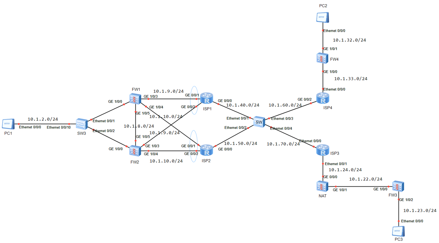 Requirement: the traffic priority is to establish IPSEC tunnel through ISP1
Interface condition
- FW1 interface fails, and the flow is switched to FW2-ISP1
- FW1 interface failure and ISP1 failure, flow switching to FW2-ISP2
- After the interface is restored, the flow returns to FW1-ISP1
Equipment condition
- When FW1 fails, flow FW2-ISP1
- When FW1 fails and ISP1 fails, flow FW2-ISP2
- When the equipment fault recovers, the flow returns to FW1-ISP1
Answer ideas
Backup mode of active and standby links
-
The headquarters firewall creates four ACL S, two of which are the same, two of which specify the headquarters to FW4 and two of which specify the headquarters to FW3
-
The headquarters firewall creates the corresponding Ike peer FW3 & FW4, where FW3 does not configure the peer address, and FW4 specifies the peer address
-
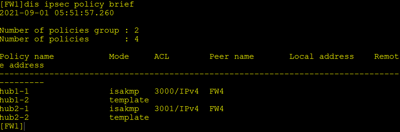
The headquarters creates two ipsec policy groups. Each policy group contains two policies for FW3 and FW4, which are called on G1/0/3 and G1/0/4 interfaces respectively
-
The headquarters invokes the policy template for the policy of FW3, and configures the tunnel local address as the VRRP address in the policy to prevent the matching failure when the headquarters is the initiator of the negotiation
-
FW1 and FW2 of the headquarters are respectively configured with two default routes, one to ISP1 and the other to ISP2. The default binding IP link to ISP1 detects the G0/0/0 interface of ISP1 and switches to ISP2 in time in case of interface failure
-
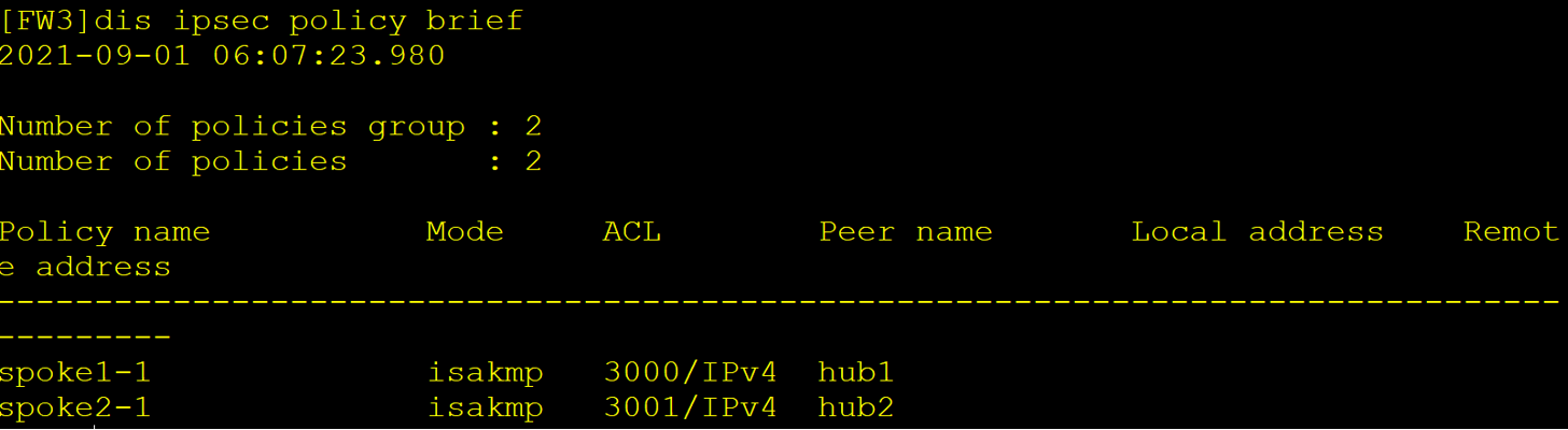
Branch FW3 is behind the NAT device, creates two tunnel interfaces, and the tunnel interface calls the physical interface address, creates two ipsec policy groups, and specifies two VRRP addresses of the opposite end respectively
-
Divide the tunnel interface into areas, configure two static routes, specify the intranet address of the opposite end, and select the tunnel interface. Two static routes, one active and one standby, are bound with IP link to detect the VRRP address of the interface between the opposite end firewall and ISP1.
-
FW4 is the same as FW3
-
Ensure the HA active standby relationship on FW1 and FW2, and ensure the normal synchronization of status information.
Command Reference
FW1 & FW2 key configurations (FW1 and FW2 are directly synchronized, so it only needs to be configured on FW1)
acl number 3000
 rule 5 permit ip source 10.1.2.0 0.0.0.255 destination 10.1.32.0 0.0.0.255
acl number 3001
 rule 5 permit ip source 10.1.2.0 0.0.0.255 destination 10.1.32.0 0.0.0.255
acl number 3002
 rule 5 permit ip source 10.1.2.0 0.0.0.255 destination 10.1.23.0 0.0.0.255
acl number 3003
 rule 5 permit ip source 10.1.2.0 0.0.0.255 destination 10.1.23.0 0.0.0.255
#
ipsec proposal hub
#
ike proposal 10
#
ike peer FW4
 pre-shared-key 123456
 ike-proposal 10
 remote-address 10.1.33.40
#
ike peer FW3
 pre-shared-key 123456
 ike-proposal 10
#
ipsec policy-template tmp1 1
 security acl 3002
 ike-peer FW3
 proposal hub
#
ipsec policy-template tmp2 1
 security acl 3003
 ike-peer FW3
 proposal hub
#
ipsec policy hub1 1 isakmp
 security acl 3000
 ike-peer FW4
 proposal hub
ipsec policy hub1 2 isakmp template tmp
#
ipsec policy hub2 1 isakmp
 security acl 3001
 ike-peer FW4
 proposal hub
ipsec policy hub2 2 isakmp template tmp
#
interface GigabitEthernet1/0/3
 ipsec policy hub1
interface GigabitEthernet1/0/4
 ipsec policy hub2
#
ip-link check enable
ip-link name ISP1
 destination 10.1.40.11 interface GigabitEthernet1/0/3 mode icmp
#
ip route-static 0.0.0.0 0.0.0.0 10.1.9.11 track ip-link ISP1
ip route-static 0.0.0.0 0.0.0.0 10.1.10.12 preference 70
#
FW3 key configuration (the same as FW4)
acl number 3000
 rule 5 permit ip source 10.1.23.0 0.0.0.255 destination 10.1.2.0 0.0.0.255
acl number 3001
 rule 5 permit ip source 10.1.23.0 0.0.0.255 destination 10.1.2.0 0.0.0.255
#
ipsec proposal FW3
#
ike proposal 10
#
ike peer hub1
 pre-shared-key 123456
 ike-proposal 10
 remote-address 10.1.9.254
#
ike peer hub2
 pre-shared-key 123456
 ike-proposal 10
 remote-address 10.1.10.254
#
ipsec policy spoke1 1 isakmp
 security acl 3000
 ike-peer hub1
 proposal FW3
#
ipsec policy spoke2 1 isakmp
 security acl 3001
 ike-peer hub2
 proposal FW3
#
interface Tunnel1
 ip address unnumbered interface GigabitEthernet1/0/0
 tunnel-protocol ipsec
 ipsec policy spoke1
interface Tunnel2
 ip address unnumbered interface GigabitEthernet1/0/0
 tunnel-protocol ipsec
 ipsec policy spoke2
#
firewall zone untrust
add interface Tunnel1
 add interface Tunnel2
#
ip-link check enable
ip-link name ISP1
 destination 10.1.9.254 interface GigabitEthernet1/0/0 mode icmp
#
ip route-static 10.1.2.0 255.255.255.0 Tunnel1 track ip-link ISP1
ip route-static 10.1.2.0 255.255.255.0 Tunnel2
Configuration result view
Tunnel link backup mode
- The headquarters creates the tunnel interface and assigns the public network address to ensure the connectivity of the underlying route
- Divide the tunnel interface into areas, and configure the static routing (detailed) output interface as tunnel
- Create two ACL S and specify the opposite end as FW4 and FW3 intranet segments respectively
- Create an IPSec policy group, and create two policy serial numbers for FW4 and FW3 respectively, of which FW3 is configured as a policy template
- Call ipsec Policy Group on Tunnel interface
- The ipsec configuration of the branch is the same as the first method
The configuration command is the same as above! Note that only one policy group needs to be configured on fw1 & FW2, and two policies can be called on the tunnel interface.