1. Lower computer program
1.1 protocol document analysis
Anonymous Kechuang gives a very detailed example on the protocol document of V7 version, so the lower computer program is very easy to write. This is the first time for the author to write the lower computer program of anonymous upper computer. Take STM32 sending an unsigned 16 bit data as an example to explain the writing of the lower computer program.
1.1.1 official agreement documents
1.1.1.1 search method
- Open the upper computer, slowly move the mouse to the left border, and wait for a while to pop up the left menu bar
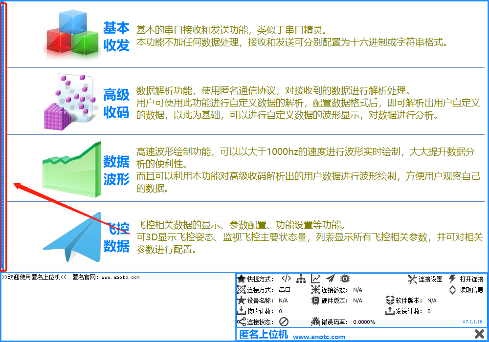
- Click the help information submenu in the pop-up menu bar
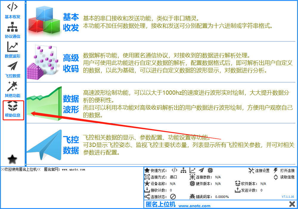
- Click communication protocol
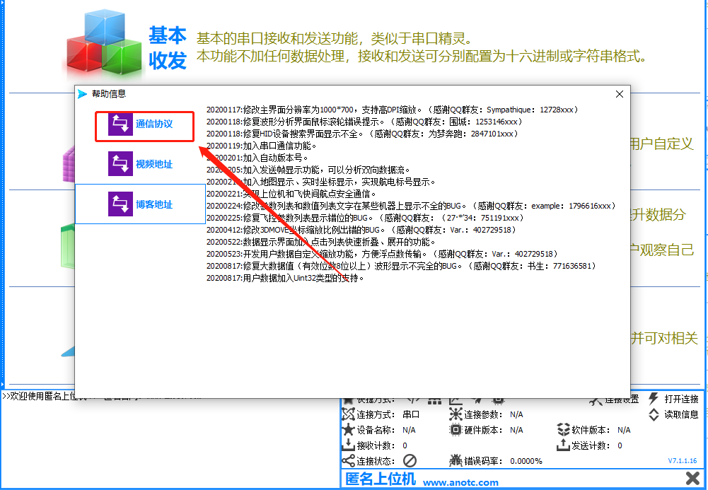
- Automatically open the file named ano using a PDF reader_ Xieyi.pdf document (if the computer does not display a PDF reader, I don't know whether it can be displayed)

1.1.1.2 analysis of lower computer protocol
1.1.1.2.1 general framework of the agreement
The lower computer protocol consists of seven parts, as shown in the figure below, including frame header (0xAA), target address, function code, data length, data content, sum verification and additional verification.
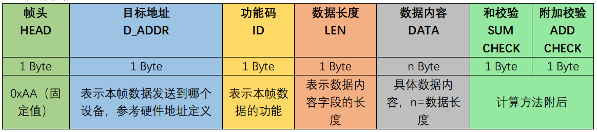
Detailed explanation of each part:
- Frame header: each packet must have a frame header, whose function is to identify the beginning of the packet.
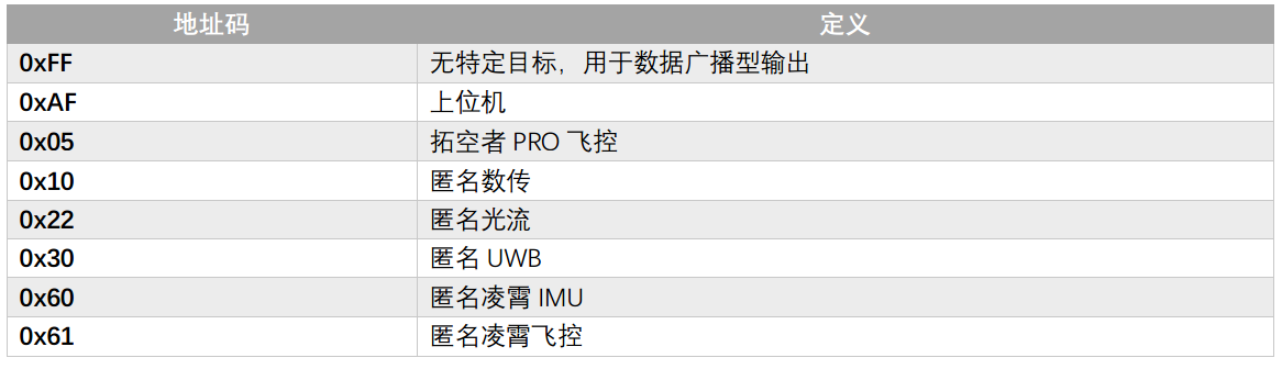
- Target address: because the anonymous communication protocol is used for the communication of all products of anonymous Kechuang, the data may be sent not only to the upper computer, but also to other devices. Therefore, this field is needed to identify which device to send data to. The specific address is described in the document
- Function code: it represents the function of the data frame. Each data frame has many functions. The function code is used as the nickname of the data.
Common function codes are as follows:
| Function code | Data name |
|---|---|
| 0x00 | Data check frame |
| 0x01 | Inertial sensor data |
| 0x02 | Compass, air pressure and temperature sensor data |
| 0x03 | Flight control attitude: Euler angle format |
| 0x04 | Flight control attitude: quaternion format |
| 0x05 | Height data |
| 0x06 | Flight control operation mode |
... and so on
- Data length: indicates the length of valid data in bytes (excluding frame header, target address, function code, data length, sum check and additional check)
- Data content: small end mode is adopted, with low byte in front, high byte in back, and one unit is one byte.
- Sum check: from 0xAA byte in the frame header to the end of the DATA area, accumulate each byte and only take the lower 8 bits
- Additional verification: during calculation and verification, each byte of addition operation is performed, and the SUM CHECK accumulation operation is performed at the same time, taking only the lower 8 bits.
Example of verification procedure:
U8 sumcheck = 0;
U8 addcheck = 0;
For(u8 i=0; I < (data_buf[3]+4); i++)
{
  sumcheck += data_buf[i];   //Starting from the frame header, sum each byte until the end of the DATA area
  addcheck += sumcheck;    //sumcheck is accumulated once for the sum operation of each byte
}
//If the calculated sumcheck and addcheck are equal to the received check data, it means that the check is passed. Otherwise, the data is incorrect
if(sumcheck == data_buf[data_buf[3]+4] && addcheck == data_buf[data_buf[3]+5])
  return true;    //Verification passed
else
  return false; //Verification failed
1.1.1.2.2 user defined data protocol analysis
Document page: 6 ~ 7
1.1.1.2.2.1 example introduction
Flexible format frame can also be called user-defined frame, that is, the data frame in which the user can define the format of data content. The use of flexible format frames may not be well understood from the name, so let's give a simple example.
I am debugging A filtering algorithm written by myself. The original data A of the sensor is in int16 format. After filtering A with the filtering algorithm, the filtered data B is obtained, and B is also in int16 format. The filtered data passes through the control algorithm and outputs A control quantity C, which is in int32 format. Then I need to debug the filtering algorithm and control algorithm. I must get the waveforms of the three ABC data and analyze the data according to the waveforms. So how to send the data ABC to the host computer for display, we need to use the flexible format frame. There are 10 flexible format frames in total, and the frame ID ranges from 0xF1 to 0xFA. Each frame can carry up to 10 data, and each data can be set to the format of U8, S16, U16 and S32 respectively. If you need to display float data, you can multiply 1000 or 100 to S32 integer for transmission according to the data range and accuracy requirements.
1.1.1.2.2.2 upper computer configuration
-
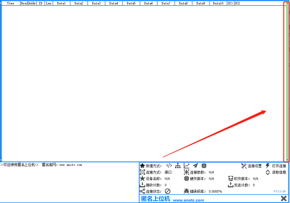
Click the protocol communication in the menu bar on the left to display the software area shown in the figure below

-
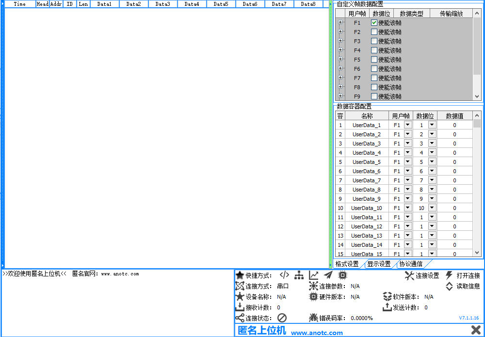
Click the border on the right
The data configuration window pops up
-
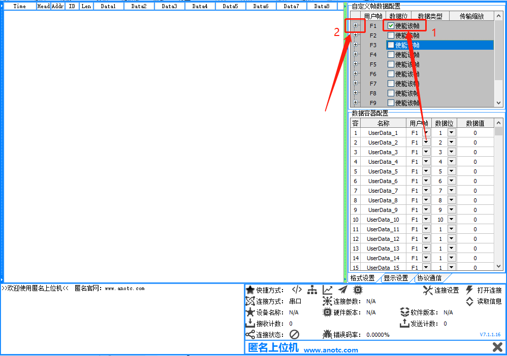
Check the selection box to the right of F1, and then click the plus sign box to the left of F1
-
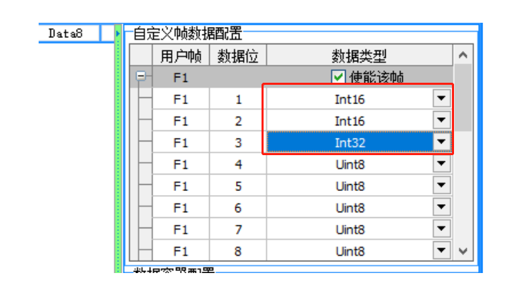
Configure the first three data types according to the following figure, which are the three data types in the example
-
We configure the data container. Data container settings, what is a data container? That is, after the F1 data frame is parsed just now, up to 30 data will be parsed. Which data is used for waveform display or which data is saved in excel? This is the data container. The anonymous upper computer is provided with 10 data containers corresponding to tabs 1 to 10 in this area. We can imagine the data container as 10 trucks. Only trucks can transmit data to users. Which data will these 10 trucks transmit to users? This is the data container configuration area for configuration.
The specific configuration is shown in the figure below:

So far, the configuration of the upper computer is completed. Only the single chip microcomputer sends the data to the upper computer according to the following protocol format, and the corresponding data value can be observed
Start refreshing and draw the corresponding data waveform.
1.1.1.2.2.3 data format of lower computer
The data is in the following format:
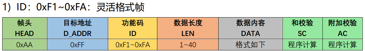
DATA area content:
To illustrate the format of the DATA area, for example, in the above, three DATA of ABC need to be sent, AB is int16, C is int32, then the three DATA of ABC are 2 + 2 + 4 = 8 bytes in total, then the LEN byte is 8, and the frame ID is 0xF1. In the DATA area, three DATA of ABC are put in turn, and then SC and AC are calculated. After that, the frame can be sent to the upper computer.
1.1.1.2.2.4 code implementation
Driver code:
ANO_DataProtocol.c
#include "usart.h"
#include "ANO_DataProtocol.h"
#include "stm32f10x.h"

#Define byte0 (dwtemp) (* (char *) (& dwtemp)) / / get the low byte of int type variable
#Define byte1 (dwtemp) (* ((char *) (& dwtemp) + 1)) / / get the contents of the next memory byte stored in this variable, high byte
#define BYTE2(dwTemp)       (*((char *)(&dwTemp) + 2))
#define BYTE3(dwTemp)       (*((char *)(&dwTemp) + 3))

void AnoTc_SendUserTest(s16 A, s16 B, s32 C)
{
	// AA 05 AF F1 02 E4 01 36
	unsigned char _cnt = 0;
	unsigned char i;
	unsigned char sumcheck = 0;
	unsigned char addcheck = 0;

	Data_to_Send[_cnt++] = 0xAA;
	Data_to_Send[_cnt++] = 0xFF;
	Data_to_Send[_cnt++] = 0xF1;
	Data_to_Send[_cnt++] = 8;
	Data_to_Send[_cnt++] = BYTE0(A);
	Data_to_Send[_cnt++] = BYTE1(A);
	Data_to_Send[_cnt++] = BYTE0(B);
	Data_to_Send[_cnt++] = BYTE1(B);
	Data_to_Send[_cnt++] = BYTE0(C);
	Data_to_Send[_cnt++] = BYTE1(C);
	Data_to_Send[_cnt++] = BYTE2(C);
	Data_to_Send[_cnt++] = BYTE3(C);

	for(i = 0; i < _cnt; i++)
	{
		sumcheck += Data_to_Send[i];
		addcheck += sumcheck;
	}
	//if(sumcheck == Data_to_Send[Data_to_Send[3]+4] && addcheck == Data_to_Send[Data_to_Send[3]+5])
	Data_to_Send[_cnt++]=sumcheck;
	Data_to_Send[_cnt++]=addcheck;
	USART_SendCharArr(USART1, Data_to_Send,_cnt);
}
ANO_DataProtocol.h
#ifndef __ANO_DATA_PROTOCOL_H__
#define __ANO_DATA_PROTOCOL_H__

#include "sys.h"

void AnoTc_SendUserTest(s16 A, s16 B, s32 C);

#endif
main.c
#include "stm32f10x.h"
#include "delay.h"
#include "sys.h"
#include "usart.h"
#include "ANO_DataProtocol.h"

int main()
{
	u16 i = 0;

    u32 ECG1,ECG2,ECG3;
    SystemInit();//Initialization of system clock, etc
    delay_init();	     //Delay initialization
    NVIC_Configuration();//Set NVIC interrupt packet 2: 2-bit preemption priority and 2-bit response priority
    uart_init(115200);//Initialize the serial port to 9600 / / delay initialization

	while(1)
	{
		for(i = 0; i < 400; i++)
		{
			AnoTc_SendUserTest(i, i+100, i+200);
			delay_ms(100);
		}
		for(i = 400; i > 200; i--)
		{
			AnoTc_SendUserTest(i, i+100, i+200);
			delay_ms(100);
		}
	}
}
2. Upper computer waveform
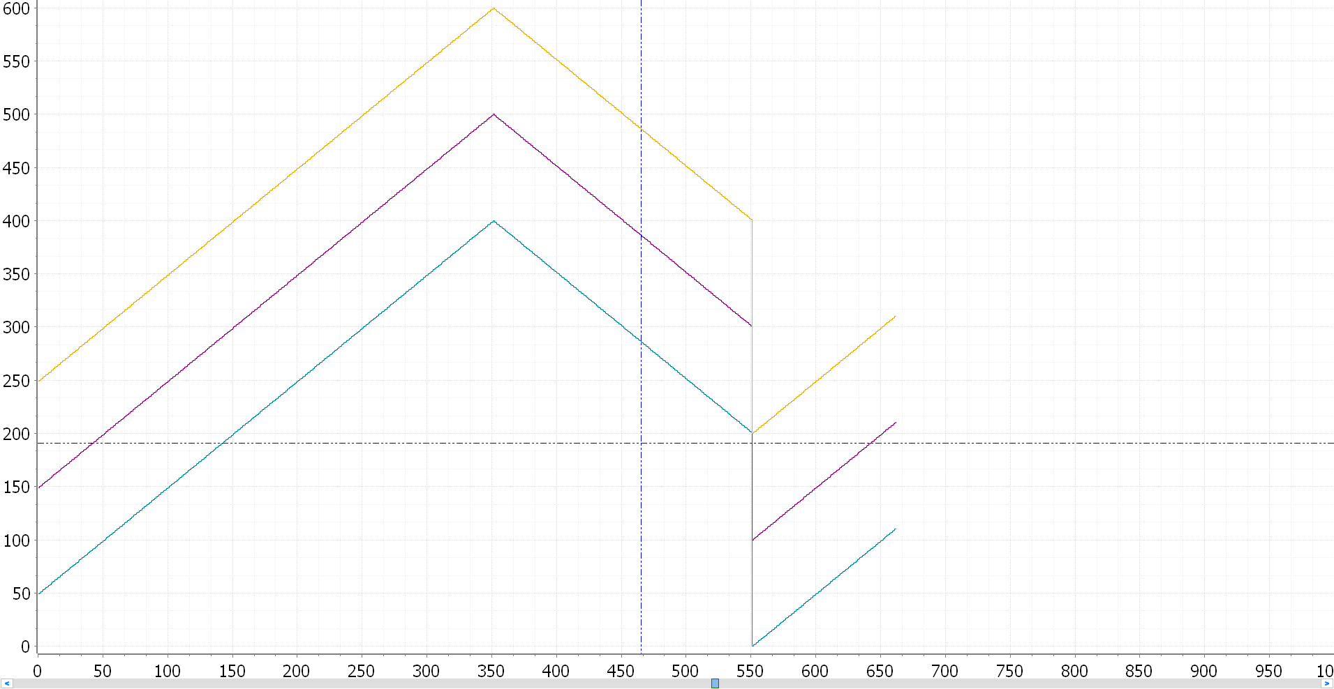
A strange triangular wave was generated
3. Resource download
Anonymous host computer waveform display demo and protocol document: https://download.csdn.net/download/FourLeafCloverLLLS/34433481