Analysis of Joint Application Example of IPsec VPN and VRRP (Virtual Gateway Technology)
 Topological requirements:
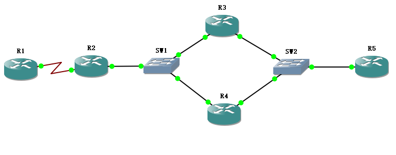
(1) VRRP virtual IP-10.1.100.254 between R1 and R3/R4 to establish Ipsec VPN
(2) R3/R4 virtual IP-10.1.200.254 is R5 gateway
Solution:
Using HSRP in R3/R4 Virtual Gateway
R1 sets only one peer
Solution to Routing Black Hole: HSRP can monitor the upstream link
Solving route asymmetry:
1) R3/R4 Hot Backup Gateway for R5
2) IPsec routing reverse injection, using dynamic routing protocol to republish static injection
1. Specific planning of IP address:
The IPV4 address of loopback 1 of R1 is 1.1.1.1/32
R2's loopback 1 IPV4 address is 2.2.2.2/32
The IP V4 address of S1/1 interface of R1-R2 is 10.1.12.1/24.
R2-R1's SI/0 interface IPV4 address is 10.1.12.2/24
The F0/0 interface IPV4 address of R2-SW 1 is 10.1.100.1/24.
R3-SW 1 F0/0 interface IPV4 address is 10.1.100.2/24
R4-SW 1 F0/0 interface IPV4 address is 10.1.100.3/24
R3-SW2 F0/1 interface IPV4 address is 10.1.200.1/24
R4-SW 2 F0/1 interface IPV4 address is 10.1.200.2/24
R5-SW2 F0/1 interface IPV4 address is 10.1.200.3/24
The IPV4 address of R 5 loopback 1 is 5.5.5/32
Note: Switch 1 and Switch 2 can be configured without any configuration.
2. The configuration is as follows:
The configuration of R1:
R1(config)#ip route 0.0.0.0 0.0.0.0 10.1.12.2

R1(config)#crypto isakmp policy 10
R1(config-isakmp)#authentication pre-share
R1(config-isakmp)#exit
R1(config)#crypto ipsec transform-set ccie esp-des esp-md5-hmac
R1(cfg-crypto-trans)#mode tunnel
R1(cfg-crypto-trans)#exit
R1(config)#crypto isakmp key cisco address 0.0.0.0
R1(config)#crypto isakmp keepalive 10 periodic
R1(config)#access-list 100 permit ip host 1.1.1.1 host 5.5.5.5
R1(config)#crypto map ccie 10 ipsec-isakmp
R1(config-crypto-map)#match address 100
R1(config-crypto-map)#set transform-set ccie
R1(config-crypto-map)#set peer 10.1.100.254
R1(config-crypto-map)#exit

R1(config)#int s1/1
R1(config-if)#crypto map ccie
Configuration of R2 (ISP):
R2(config)#int loop 1
R2(config-if)#ip address 2.2.2.2 255.255.255.255
R2(config)#exit
R3 configuration:
R3(config)#ip route 0.0.0.0 0.0.0.0 10.1.100.1
R3(config)#ip route 5.5.5.5 255.255.255.255 10.1.200.3

R3(config)#int f0/0
R3(config-if)#standby 1 ip 10.1.100.254
R3(config-if)#standby 1 preempt
R3(config-if)#standby 1 priority 120
R3(config-if)#standby 1 track f0/1
R3(config-if)#standby 1 name ccie
R3(config-if)#exit
R3(config)#int f0/1
R3(config-if)#standby 1 ip 10.1.200.254
R3(config-if)#standby 1 preempt
R3(config-if)#standby 1 priority 120
R3(config-if)#standby 1 track f0/0

R3(config)#crypto isakmp policy 10
R3(config-isakmp)#authentication pre-share
R3(config-isakmp)#exit
R3(config)#crypto isakmp key cisco address 0.0.0.0
R3(config)#crypto isakmp keepalive 10 periodic
R3(config)#crypto ipsec transform-set ccie esp-des esp-md5-hmac
R3(cfg-crypto-trans)#mode tunnel
R3(cfg-crypto-trans)#exit
R3(config)#access-list 100 permit ip host 5.5.5.5 host 1.1.1.1
R3(config)#crypto map ccie 10 ipsec-isakmp
R3(config-crypto-map)#match address 100
R3(config-crypto-map)#set transform-set ccie
R3(config-crypto-map)#set peer 10.1.12.1
R3(config-crypto-map)#exit

R3(config)#int f0/0
R3(config-if)#crypto map ccie redundancy ccie
The configuration of R4 is the same as that of R3 (the HSRP protocol status of R4 is standy)
R5 configuration:
R5(config)#ip route 0.0.0.0 0.0.0.0 10.1.200.254
After the configuration is completed, the connectivity of R1-R5 is detected:
R1#ping 5.5.5.5 source 1.1.1.1

Type escape sequence to abort.
Sending 5, 100-byte ICMP Echos to 5.5.5.5, timeout is 2 seconds:
Packet sent with a source address of 1.1.1.1
!!!!!
Success rate is 100 percent (5/5), round-trip min/avg/max = 8/20/32 ms
Creator: Eric Charles