outline
This paper mainly records some personal opinions on learning I2C protocol, and realizes STM32 to read and write EEPROM data based on I2C protocol
Statement: due to limited personal ability, this article is only personal learning notes, and I hope to point out any mistakes

I2C characteristics
- Support device bus, that is, multiple devices can share signal lines. Multiple I2C communication devices can be connected in one I2C communication bus to support multiple communication hosts and multiple passing slaves
- Two bus lines are used, one bidirectional serial data line (SDA) and one serial clock line (SCL). SCL is used for synchronization of data sending and receiving
- Each device connected to the bus has an independent address through which different devices can be accessed
- The bus is connected to the power supply through the pull-up resistor. When the I2C device is idle, it will output the high resistance state. When all devices are idle, it will output the high resistance state. The pull-up resistor will pull the bus to the high level
- When multiple hosts use the bus, arbitration will be used to determine which device occupies the bus
Basic reading and writing process of I2C
The master writes data to the slave

The host reads data from the slave

- When the master communicates with the slave, S indicates the transmission start signal generated from the I2C interface of the master. At this time, all slaves connected to the I2C bus will receive the signal.
- In order to realize the slave with correct operation, the SLAVE ADDRESS broadcast by the host is unique on the I2C bus, so the slave is selected. (the SLAVE ADDRESS can be 7 bits or 10 bits)
- After successfully finding the slave, the selection bit of the transmission direction. When this bit is 0, it means that the host writes data to the slave. When this bit is 1, it means that the host reads data to the slave (0 writes and 1 reads)
- After the slave receives the matching address, the master or slave returns an ACK or NACK signal, and can continue to send or receive data only after receiving the ACK signal.
Write data
The configuration direction transmission bit is "write DATA" direction (0). After broadcasting the address and receiving the response signal, the host officially starts to write DATA (DATA) to the slave. The DATA packet size is 8 bits. Each time the host sends one byte of DATA, it must wait for the response signal (ACK) from the slave. Repeat this process to transmit N DATA to the slave. Finally, when the transmission ends, The master sends a stop transmission signal to the slave, indicating that DATA is no longer transmitted.
Read data
The configuration direction transmission bit is "read DATA" direction (1). After broadcasting the address and receiving the response signal, the host officially starts to write DATA (DATA) to the slave. The DATA packet size is 8 bits. Each time the host sends one byte of DATA, it must wait for the response signal (ACK) from the slave. Repeat this process to transmit N DATA to the slave. When the master wants to stop receiving DATA, the slave can return a non reply signal (NACK), and the slave will automatically stop DATA transmission
Read and write data
In addition to basic reading and writing, I2C communication is more commonly used in composite mode, which has two start signals (S). Generally, in the first transmission, the host passes slave_ After finding the slave device, address sends a piece of data, which represents the internal memory or memory address of the slave device (pay attention to distinguish it from SLAVE_ADDRESS); In the second transmission, the content of the changed address is read and written.
In short, the read-write address is transmitted for the first time, and the specific data is read-write for the second time
Initial state of I2C

- start
SCL is high level and SDA is converted from high level to low level
/* SCL It is high level, and a next skip edge appears */
void I2C_Start(void){
	SDA_HIGH();
	SCL_HIGH();
	delay();
	SDA_LOW();
	delay();
	SCL_LOW():
	delay();
}
- end
SCL is high level, and SDA is converted from low level to high level
/* SCL It is high level, and there is an up jump edge */
void I2C_Stop(void){
	SDA_LOW();
	SCL_HIGH();
	delay();
	SDA_HIGH();
}
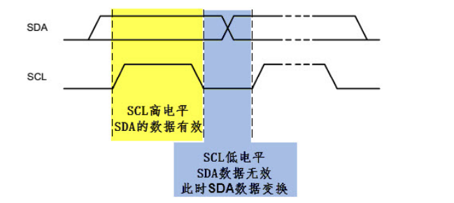
3. Validity of data
SDA data line transmits one bit of data (8 bytes) in each clock cycle of SCL. When SCL is high level, the data represented by SDA is valid. At this time, SDA is high level, indicating data "1" and low level, indicating data "0"; When SCL is at low level, SDA data is invalid. Generally, SDA performs level switching at this time to prepare for the next data.
Transmit data
- Byte format
Each byte sent to the SDA line must be 8 bits. The number of bytes that can be sent each time is unlimited, but each byte must be followed by a response bit

- response
Data transmission must have response, and the corresponding response clock is generated by the host. The response includes "reply" (ACK) and "non reply" signal (NACK). In the ninth clock, the transmitter releases SDA line (high). SDA high level represents non response signal, SDA low level represents response signal, and SCL line will generate a clock signal by converting high and low levels.
EEORPM
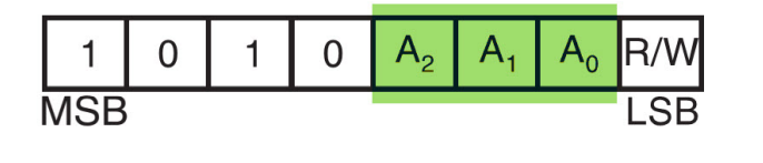
The EEPROM chip (AT24C02) used in this experiment grounded A0/A1/A2, so the 7-bit address of the equipment address is 0x50 (1010000), the read address is 0xA1 (10100001), and the write address is 0xA0 (10100000); I2C is realized by software simulation.
Programming flow
- Configure peripheral pins
- Write control functions that simulate I2C timing
- Write basic I2C read-write functions
- Write a function to read and write the contents of EEPROM here
- Write test functions
code implementation
Software simulation I2C
void I2C_Delay(void){
	uint8_t i;
	for(i=10;i>0;i--);
}
/* I2C Start signal */
void EEPROM_I2C_Start(void){
	//SCL is high level and SDA has a falling edge
	SDA_HIGH();
	SCL_HIGH();
	I2C_Delay();
	SDA_LOW();
	I2C_Delay();
	SCL_LOW();
	I2C_Delay();
}
/* I2C End signal */
void EEPROM_I2C_Stop(void){
	//SCL is high level and SDA has a rising edge
	SDA_LOW();
	SCL_HIGH();
	I2C_Delay();
	SDA_HIGH();
	I2C_Delay();
}
/* I2C Response signal */
void EEPROM_I2C_ACK(void){
	SDA_LOW();		//Response signal
	I2C_Delay();
	SCL_HIGH();//The CPU generates a clock
	I2C_Delay();
	SCL_LOW();//The CPU generates a clock
	I2C_Delay();
	SDA_HIGH();			//CPU releases SDA line

}
/* I2C Non response signal */
void EEPROM_I2C_NACK(void){
	SDA_HIGH();		//Non response signal
	I2C_Delay();
	SCL_HIGH();//The CPU generates a clock
	I2C_Delay();
	SCL_LOW();//The CPU generates a clock
	I2C_Delay();
}

/* I2C Waiting for response */
uint8_t EEPROM_I2C_WaitAck(void){
	//A return of 0 indicates a correct response, and a return of 1 indicates no device response
	uint8_t re;

	SDA_HIGH();		//CPU releases SDA bus
	I2C_Delay();
	SCL_HIGH();//The CPU generates a clock
	I2C_Delay();

	//At this time, the CPU reads the status of SDA port (SDA low level returns reply and high level returns non reply)
	if(EEPROM_I2C_SDA_Read())
		re = 1;
	else
		re = 0;
	SCL_LOW();
	I2C_Delay();
	return re;
}

/* CPU Send 8bit data to I2C bus */
void I2C_SendByte(uint8_t Byte){

	uint8_t i;

	//Send the high bit bit7 of the byte first
	for(i = 0; i < 8 ;i++){
		if(Byte & 0x80)	//Judge the highest logical value
			SDA_HIGH();
		else
			SDA_LOW();
		I2C_Delay();

		SCL_HIGH();//The CPU generates a clock
		I2C_Delay();
		SCL_LOW();
		if( i == 7)
			SDA_HIGH();	//After the last data transmission is completed, release the bus

		Byte <<= 1; 	//Shift one bit to the left to facilitate the next cycle of sending the next bit of data
		I2C_Delay();

	}
}
/* CPU Read 8bit data from I2C bus */
uint8_t I2C_ReadByte(void){
	uint8_t i,value;
	value = 0;
	//Read that the first bit is bit7 of data
	for(i = 0; i < 8 ;i++ ){
		value <<= 1;		//Serial read
		SCL_HIGH(); //Generate a clock
		I2C_Delay();
		if(EEPROM_I2C_SDA_Read())
			value++;

		SCL_LOW();
		I2C_Delay();
	}
	return value;
}
I2C read / write EEPROM
//Check I2C equipment
uint8_t ee_CheckDevice(uint8_t _Address){
	uint8_t ucAck;

	//Send start signal
	I2c_Start();

	//Sending device address + read / write control bit
	I2c_SendByte(_Address|EEPROM_I2C_WR);
	ucAck=i2c_WaitAck();


	I2c_Stop();	/* Send stop signal */
	i2c_NAck();	/*If the input is a read address, a non reply signal needs to be generated*/
	return ucAck;
}

/*
*	Function: wait for EEPROM to be ready. This function must be called after writing data
*				During write operation, after using I2C to transfer data to EEPROM,
*				EEPROM It takes some time to write data to the internal space,
*				When EEPEOM is written, it will respond to I2C device addressing
*
*				Call this function to wait until the internal timing of EEPROM is written
*/
u8	ee_WaitStandby(void){
	u32	wait_count=0;

	while(ee_CheckDevice(EEPROM_DEV_ADDR))
	{
		//If the detection times exceed, exit the cycle (avoid dead cycle)
		if(wait_count ++ >0xFFFF)
			//Wait timeout
			return 1;
	}
	return 0;
}
/*
*	Function: write several data to the specified address of Serial EEPROM. Using page operation can improve the writing efficiency
*
*	Formal parameters: 	_ usAddress: starting address
*				_usSize:Data length, in bytes
*				_pWriteBuf:Pointer to the buffer that holds the read data
*/
u8	ee_WriteBytes(u8 *_pWriteBuf,u16 	_usAddress,u16 _usSize){
	u16 i,m,usAddr;
	/*
	Unlike the read operation, writing Serial EEPROM can read many bytes continuously. Each operation can only be written on the same page
	Corresponding to 24xx02 chip, page size =8;
	The simple processing method is: according to the byte write operation mode, each byte is written and the address is sent
	Improve efficiency by using page write

	*/
	usAddr = _usAddress;
	for(i=0;i<_usSize;i++){

		//When sending the first byte or the first address of the page, it is necessary to re send the start signal and address
		if((i==0)||(usAddr&(EEPROM_PAGE_SIZE-1))==0){
			//Step 0: Send a stop signal to end the communication on the previous page and prepare for the next communication
			I2c_Stop();
			/*	Judge whether the internal write operation is completed by checking the device response, which is generally less than 10ms
			CLK When the frequency is KHz, the number of queries is about 30
			Principle and ee_WaitStandby() function, but the function will generate a stop signal after the check is completed,
			Not applicable here
			*/
			for(m=0;m < 1000; m++){
			//Step 1: send I2C bus signal

				I2c_Start();

			//Step 2: initiate the control byte. The high 7bit is the address, bit0 is the read-write control bit, 0: write, 1: read

				I2c_SendByte(EEPROM_DEV_ADDR|EEPROM_I2C_WR);

			//Step 3: Send a clock to judge whether the device responds correctly
					if(i2c_WaitAck() == 0)
							break;
				}
				if(m == 1000)
						goto cmd_fail;//EEPROM device write timeout

				//Step 4: send byte address. 24c02 has only 256 bytes, so one byte is enough. If it is of other models\
				To send multiple addresses
				I2c_SendByte((u8)usAddr);
				//Step 5: wait for ACK
				if(i2c_WaitAck() != 0)
				{
						goto cmd_fail;//EEPROM device no response
				}
			}
				//Step 6: start writing data
				I2c_SendByte(_pWriteBuf[i]);

				//Step 7: send ACK
				if(i2c_WaitAck() != 0)
						goto cmd_fail;//EEPROM device no response

				usAddr++;		//Add 1 address
			}
			//If the command is executed successfully, send I2C bus stop signal
			I2c_Stop();

			//Wait for the last EEPROM internal write to complete
				if(ee_WaitStandby() == 1)
						goto cmd_fail;
			return 1;

cmd_fail:	/* 	After the command fails, remember to send a stop signal to avoid affecting other devices on the I2C bus*/
		I2c_Stop();
		return 0;
}


/*
*	Function: read several data from the specified address of Serial EEPROM
*
*	Formal parameters: 	_ usAddress: starting address
*				_usSize:Data length, in bytes
*				_pReadBuf:Pointer to the buffer that holds the read data
*/
u8	ee_ReadBytes(u8 *_pReadBuf,u16	_usAddress,u16 _usSize){
	u16 i;

	//Step 1: initiate I2C bus start signal
	I2c_Start();

	//Step 2: initiate the control byte. The top seven bits are the address, and the last bit is the read-write bit. 0: write, 1: read
	I2c_SendByte(EEPROM_DEV_ADDR|EEPROM_I2C_WR);//Write direction, write address

	//Step 3: wait for ACK
	if(i2c_WaitAck() != 0)
			goto cmd_fail;		//EEPROM device no response

	//Step 4: send byte address. 24c02 has only 256 bytes, so one byte is enough
	I2c_SendByte((u8)_usAddress);

	//Step 5: wait for ACK
	if(i2c_WaitAck() != 0)
			goto cmd_fail;		//EEPROM device no response

	//Step 6: restart I2C bus
	//The previous purpose is to transfer the address to EEPROM in the future. Now start reading the data
	I2c_Start();

	//Step 7: send control byte
	I2c_SendByte(EEPROM_DEV_ADDR|EEPROM_I2C_RD);

	//Step 8: send ACK
	if(i2c_WaitAck() != 0)
			goto cmd_fail;		//EEPROM device no response

	//Step 9: read data circularly
	for(i = 0; i < _usSize; i++){

		_pReadBuf[i]=i2c_ReadByte();//Read a byte

		//After reading one byte at a time, you need to send ack. For the last byte, you don't need to send ACK and send NACK
		if(i != _usSize -1)
				i2c_Ack();
		else
			i2c_NAck();
	}

	//Send stop signal
	I2c_Stop();
	return 1;	//Successful execution
cmd_fail:	//If the command fails to execute, remember to send a stop signal to avoid affecting other devices on the I2C bus
	//I2C bus stop signal
	I2c_Stop();
	return 0;
}
EEPROM read / write test
//EPROM read / write test
u8 ee_test(void){
u16 i;
u8 writebuf[EEPROM_SIZE];
u8 readbuf[EEPROM_SIZE];
if(ee_CheckDevice(EEPROM_DEV_ADDR)==1){
printf("Serial not detected EEPROM\r\n");
return 0;
}
//Fill buffer
for(i = 0;i < EEPROM_SIZE; i++)
writebuf[i]=i;
//write
if(ee_WriteBytes(writebuf,0,EEPROM_SIZE) == 0){
printf("write EEPROM error\r\n");
return 0;
}else
printf("write EEPROM success\r\n");
//read
if(ee_ReadBytes(readbuf,0,EEPROM_SIZE) == 0){
printf("read EEPROM error\r\n");
return 0;
}else
printf("read EEPROM success\r\n");
//Output read data (inconsistent)
printf("readbuf:\n");
for(i=0;i<EEPROM_SIZE ; i++){
if(readbuf[i] != writebuf[i]){
printf("0x%02X ", readbuf[i]);
printf("Error: EEPROM The read and written data are inconsistent\r\n");
return 0;
}
if((i % 16)== 0&&(i != 0))
printf("\n");
printf(" %02X", readbuf[i]);
}
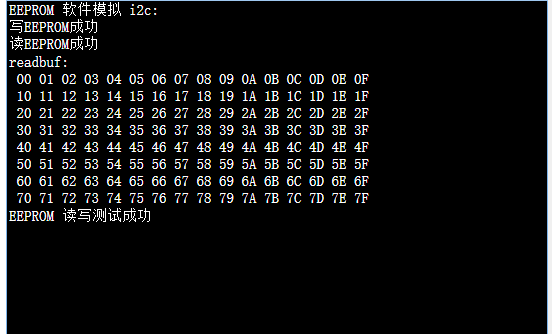
printf("\nEEPROM Read / write test successful\r\n");
return 1;
}
hardware configuration
SDA–>PB7
SCL–>PB6
Result diagram
The data of 1 ~ 128 are successfully written to EEPROM and read