Arduino based air mouse for DIY gesture control using accelerometer
Pass by** Madhav **Revised on June 24, 2019
Once wanted to know how our world is moving towards immersive reality. We have been looking for new methods and methods to interact with the surrounding environment using virtual reality, hybrid reality, augmented reality and so on. Every day, with the emergence of these fast start technologies, new devices continue to emerge, and their new interaction technology has left a deep impression on us.
These immersive technologies are used in games, interactive activities, entertainment and many other applications. In this tutorial, we will learn about this interactive method, which provides you with a new way to interact with the system without using a boring mouse. Our game geeks must know that Nintendo sold the idea of a 3D interactive method a few years ago, which interacts with the console with a handheld controller called the Wii controller. It uses accelerometers to locate your game gestures and send them wirelessly to the system. If you want to know more about this technology, you can check its patents EP1854518B1 , this will give you a complete understanding of how this technology works.
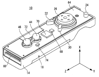 Nintendo Wii module
Inspired by this idea, we will make a * * "air mouse" * * which can interact with the system only by moving the console in the air, but we will only use two-dimensional coordinate reference instead of three-dimensional coordinate reference, so we can imitate the action of computer mouse, because the mouse works on X and Y dimensions.
The concept of this wireless 3D air mouse is very simple. We will use an accelerometer to obtain the acceleration value of the action and motion of the "air mouse" along the x and y axes. Then, based on the accelerometer, we will control the mouse cursor and perform some operations under the control of the python software driver running on the computer.
precondition
- Arduino Nano (any model)
- Accelerometer ADXL335 module
- Bluetooth HC-05 module
- Press the button
- Computer with Python installed
To learn more about installing python on your computer, follow Arduino-Python LED Controling Previous tutorial on.
Circuit diagram
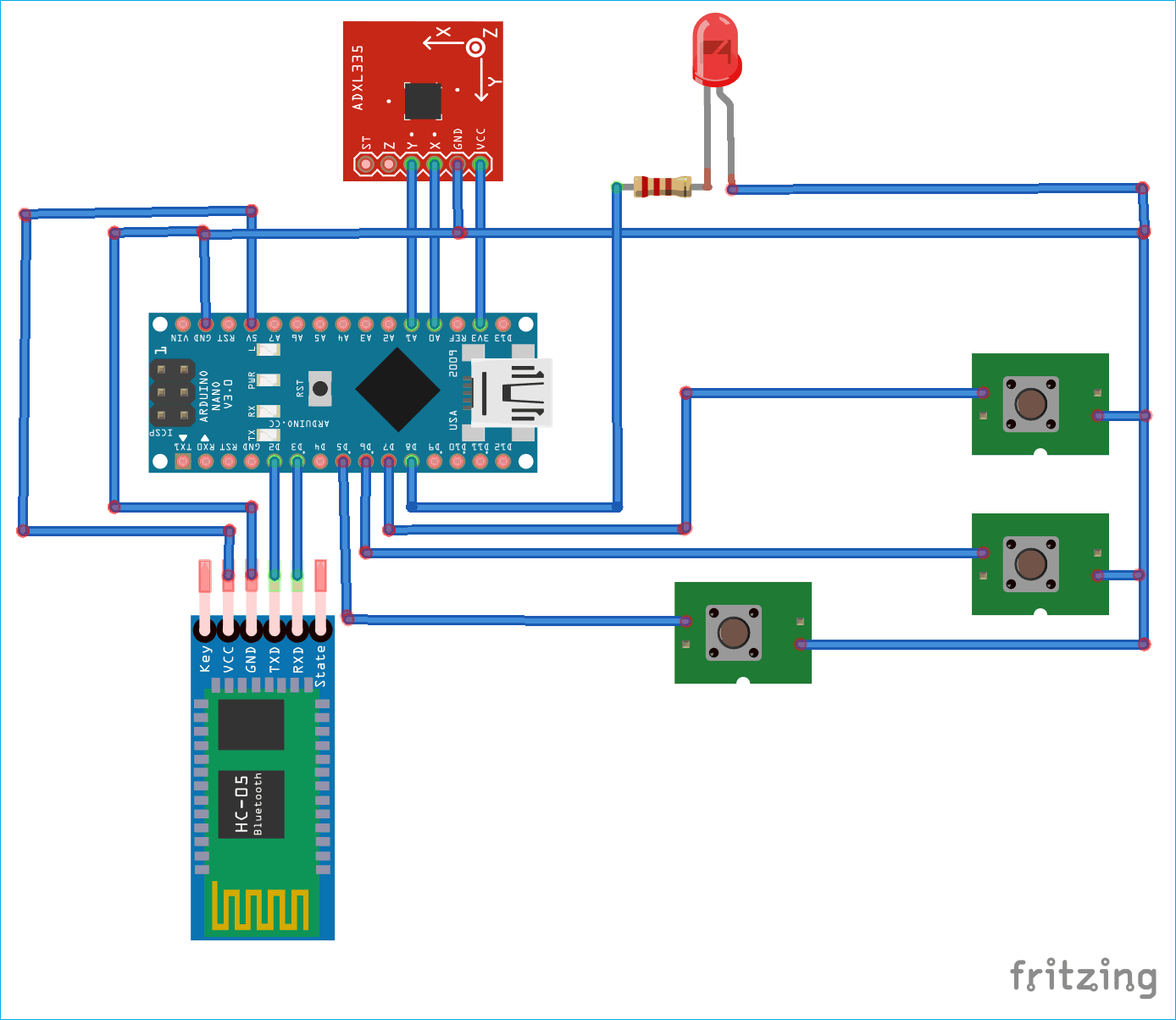
* * to control the motion of the whole computer along the X-axis and the Y-axis of the accelerometer, you need to use your Bluetooth accelerometer to send a wireless signal to the whole computer * *.
The ADXL335 accelerometer used here is a three-axis module based on MEMS, which can output the acceleration along the X, y and Z axes. However, as mentioned earlier, when controlling the mouse, we only need the acceleration along the X and Y axes. Learn more about using ADXL335 accelerometer with Arduino in previous projects:
- Arduino based vehicle accident warning system using GPS, GSM and accelerometer
- Ping Pong with Arduino and accelerator
- Using Arduino's accelerometer based gesture control robot
- Alarm using Arduino's seismic detector
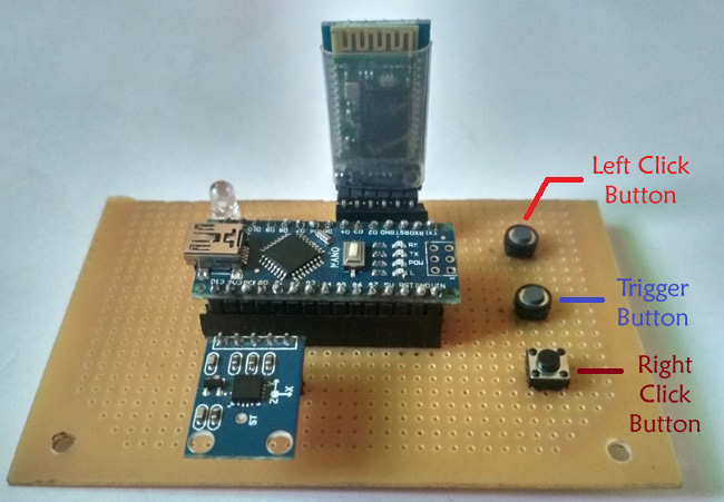
Here, the Xout and Yout pins of the accelerometer are connected to the Analog, A0 and A1 pins of Arduino, and are used to transmit signals from Arduino to the system Bluetooth module HC-05. Because Bluetooth works on Tx and Rx, the pins are connected, so we use Software serial Pins D2 and D3. It uses software serial connection, because if we connect Bluetooth with hardware serial connection and start to get readings through the python console, the error of baud rate mismatch will be displayed because Bluetooth will communicate with Python at its own baud rate. By using different microcontrollers including Arduino Various Bluetooth based projects To learn more about using the Bluetooth module.
Here, we use three buttons - one to trigger the Air mouse and the other two to click left and right, as shown in the figure below:
Processing flow of air mouse
The flow chart shows the processing flow of Air Mouse based on Arduino:
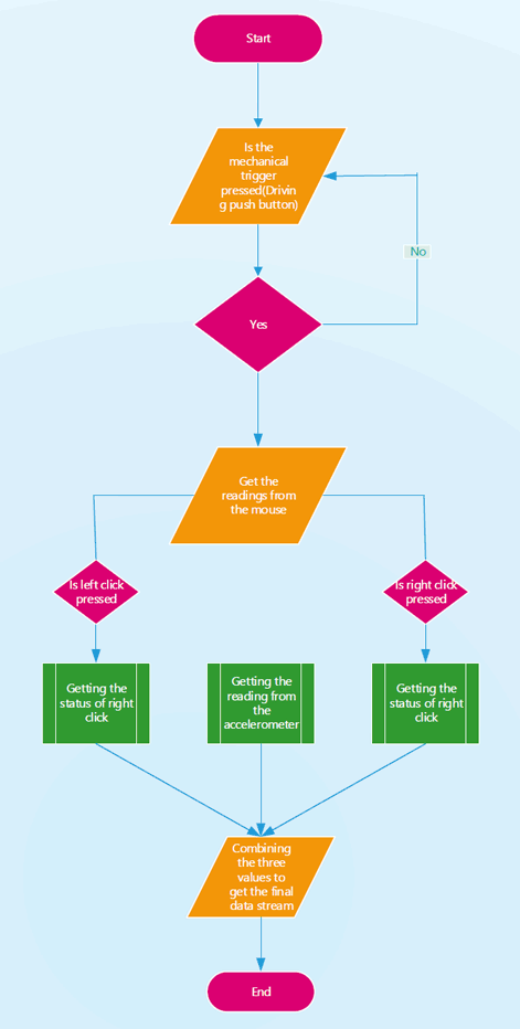
1. The system will continuously check whether to press the mechanical trigger. We can't operate normally with the computer mouse until the mechanical trigger is not pressed.
2. When the system detects that the button is pressed, the control of the mouse will be transferred to the air mouse.
3. After pressing the trigger button, the system starts to transmit the reading of the mouse to the computer. System readings consist of accelerometer readings and left - and right-click readings.
4. The system reading consists of a 1-byte or 8-bit data stream, in which the first three bits are composed of X coordinates, the last three bits are composed of Y coordinates, the second bit is the status bit to be obtained, the left mouse click status, and the last bit is the status bit to obtain the right-click status.
5. The value of the first three bits (i.e. X coordinate) can be in the range of 100 < = xcord < = 999, while the value of Y coordinate can be in the range of 100 < = ycord < = 800. The right - and left-click values are binary values 0 or 1, where 1 indicates a click and 0 indicates that the user did not click.
6. In order not to Button of bounce Affecting the position of the cursor, each time you click the trigger button of the mouse, it will maintain a known delay of 4 seconds.
7. For left and right clicks in the air mouse, we must first press the left or right button, and then we must press the trigger button to move to the desired position of the air mouse.
Programming Arduino for Air Mouse
Arduino should be programmed to read the acceleration values on the X and Y axes. Finally, the complete program is given. The following are important fragments of the code.
Set global variables
As mentioned earlier, we will use the software serial pin to connect the Bluetooth module. Therefore, to set the software sequence, we need to declare the software sequence library and set the pins of Tx and Rx. In Arduino Nano and Uno, Pin 2 and 3 can be used as software sequences. Next, we declare the Bluetooth object from the software serial library to set the pins of Tx and Rx.
#include <SoftwareSerial.h>
const int rxpin = 2, txpin = 3;
SoftwareSerial bluetooth(rxpin, txpin);
const int x=A0;
const int y=A1;
int xh, yh;
int xcord, ycord;
const int trigger = 5;
int lstate = 0;
int rstate = 0;
const int lclick = 6;
const int rclick = 7;
const int led = 8;
void setup()
In the setup function, we will set variables to tell the program whether they will act as input or output. The trigger button will be set to input pull-up, while the left and right keys will be declared as inputs and set to high level to act as input pull-up.
Also set the baud rate of serial and Bluetooth communication to 9600.
  void setup()
{
  pinMode(x,INPUT);
  pinMode(y,INPUT);
  pinMode(trigger,INPUT_PULLUP)
  pinMode(lclick,(input);
  pinMode(rclick,INPUT);
  pinMode(led,OUTPUT);
  digitalWrite(lclick,HIGH);
  digitalWrite(rclick,HIGH);
  Serial.begin(9600);
  bluetooth.begin(9600);
}
void loop()
Because we need the trigger button to tell us when to send data flow to the system, we set the whole code in the while loop. The code will continuously monitor the digital state of the pull-up trigger. When it goes low, it will further pass it for processing.
Since we have installed LED indicators to understand the system status when the trigger button is pressed, we initially set the led to low in the default state outside the while cycle and high in the while cycle *, * which will make the LED light up whenever the trigger button is pressed.
To read the status of the left-right click button * *, * * we have globally declared two variables lclick and rclick, whose values are initially set to 0.
Then, in the loop, set the values of these variables according to the digital state of the left-right click button to check whether the button is pressed.
We will use the AnalogRead function to read the values of the X and Y out pins of the accelerometer and map these values to the screen size to move the mouse pointer across the screen. Since the screen size is the pixel in the screen, we need to set it accordingly, and because we need to set the output value to three digits, we specially set the range of X to 100 < = x < = 999. The value of Y is 100 < = y < = 800. Remember that the pixel is read from the upper left corner, that is, the value of the upper left corner is (0,0), but since we have declared the three digits of X and y, the value will be read from the point (100100).
In addition, with the help of serial Print and Bluetooth The print function can print coordinate values and click status on serial and Bluetooth, which help to obtain these values on serial monitors and systems through Bluetooth.
This may cause the cursor to jump on the last position of a single button, which may lead to the elimination of this value.
void loop()
{
digitalWrite(led,LOW);
  while(digitalRead(trigger)==LOW)
  {
    digitalWrite(led, HIGH);
    lstate = digitalRead(lclick);
    rstate = digitalRead(rclick);
    xh=analogRead(x);
    yh=analogRead(y);
    xcord=map(xh,286,429,100,999);
    ycord=map(yh,282,427,100,800);
    Serial.print(xcord);
    Serial.print(ycord);
    if (lstate == LOW)
    Serial.print(1);
    else
    Serial.print(0);
    if (rstate == LOW)
    Serial.print(1);
    else
    Serial.print(0);
    bluetooth.print(xcord);
    bluetooth.print(ycord);
    if (lstate == LOW)
    bluetooth.print(1);
    else
    bluetooth.print(0);
    if (rstate == LOW)
    bluetooth.print(1);
    else
    bluetooth.print(0);
    delay(4000);
   } }
* * * * Python driver script for computer
So far, we have completed the hardware and firmware. Now to make the air mouse work normally, we need a driver script that can decode the signal from the air mouse into cursor movement. Therefore, we chose python. Python is a scripting language. The script here means that it can help us control other programs, because here we want to control the mouse cursor.
Therefore, open your python shell and install the following libraries using the following command:
pip install serial
pip install pyautogui
The * * * series * is a python library that helps us get rid of the data of serial interfaces such as COM ports, and also allows us to operate them. While * pyautogui * * * is a library Python and is controlled by GUI functions. In this case, the mouse.
Now let's look at the driver code. The first thing we need to do is import the serial and pyautogui libraries. Then from the serial library, we must set the com port for communication at the baud rate of 9600, that is, with Bluetooth Serial is the same. To do this, you must connect the Bluetooth module to the system and then check which com port it is connected to in the system settings.
The next thing is to read the serial communication from Bluetooth to the system and keep it running continuously, and keep the rest of the code in a continuous loop with the help of while 1.
As mentioned earlier, Arduino will send 8 bits, the first 6 bits are used for coordinates, and the last two bits are used for the status of clicking the button. Therefore, in Ser With the help of read, read all bits and set their length to 8 bits.
Next, the cursor coordinates and the clicked position are divided into multiple parts, and then further divided into X and Y coordinates. Left click and right click are the same.
Now, from the communication, we get a byte string. We need to convert it to integers so that they fit the coordinates. We do this by decoding them and then converting their type to integers.
Now to move the cursor, we use the pyautogui moveto function, which takes those integer coordinates as parameters and moves the cursor to that position.
Next, check the clicks. We use the click function of the last two bits and pyautogui to complete it. The default click is left, but we can set it to right by declaring the button value as right. We can also define the number of clicks and set it to double-click by setting the clicks parameter to 2.
Here is the complete Python code to run on your computer:
import serial
import pyautogui
ser=serial.Serial('com3',9600)
while 1:
    k=ser.read(8)
    cursor=k[:6]
    click=k[6:]
    x=cursor[:3]
    y=cursor[3:]
    l=click[0]
    r=click[1]
    xcor=int(x.decode('utf-8'))
    ycor=int(y.decode('utf-8'))
    pyautogui.moveTo(xcor,ycor)
    if l==49:
        pyautogui.click(clicks=2)
    elif r==49:
        pyautogui.click(button='right', clicks=2)
Test Arduino Air Mouse
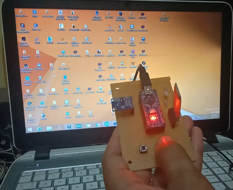
Therefore, to operate the Air Mouse, connect the power supply to it. It can come from the Arduino Nano USB slot or from a 5v regulated power supply using the 7805 IC. Then run the python driver script by setting the com port of the Bluetooth connection. When the script runs, you will see a time lag in the Bluetooth flash, which means that it is connected to your system. Then, operate it and click the "trigger" button. You will see that the position of the coordinates will change; If you want to click the left or right button, first press the left or right button and the trigger button at the same time, and you will see the action you clicked in the following position: the position of the cursor has changed.

See the detailed work video below.
Python Script:
import serial
import pyautogui
ser=serial.Serial('com3',9600)
while 1:
    k=ser.read(8)
    cursor=k[:6]
    click=k[6:]
    x=cursor[:3]
    y=cursor[3:]
    l=click[0]
    r=click[1]
    xcor=int(x.decode('utf-8'))
    ycor=int(y.decode('utf-8'))
    pyautogui.moveTo(xcor,ycor)
    if l==49:
        pyautogui.click(clicks=2)
    elif r==49:
        pyautogui.click(button='right', clicks=2)
Arduino Code:
#include <SoftwareSerial.h>
const int rxpin = 2, txpin = 3;
SoftwareSerial bluetooth(rxpin, txpin);
const int x=A0;
const int y=A1;
int xh, yh;
int xcord, ycord;
const int trigger = 5;
int lstate = 0;
int rstate = 0;
const int lclick = 6;
const int rclick = 7;
const int led = 8;

void setup()
{
  pinMode(x,INPUT);
  pinMode(y,INPUT);
  pinMode(trigger,INPUT_PULLUP);
  pinMode(lclick,INPUT);
  pinMode(rclick,INPUT);
  pinMode(led, OUTPUT);
  digitalWrite(lclick,HIGH);
  digitalWrite(rclick,HIGH);
  Serial.begin(9600);
  bluetooth.begin(9600);
}

void loop()
{
digitalWrite(led,LOW);
  while(digitalRead(trigger)==LOW)
  {
    digitalWrite(led, HIGH);
    lstate = digitalRead(lclick);
    rstate = digitalRead(rclick);
    xh=analogRead(x);
    yh=analogRead(y);
    xcord=map(xh,286,429,100,999);
    ycord=map(yh,282,427,100,800);
    Serial.print(xcord);
    Serial.print(ycord);
    if (lstate == LOW)
    Serial.print(1);
    else
    Serial.print(0);
    if (rstate == LOW)
    Serial.print(1);
    else
    Serial.print(0);
    bluetooth.print(xcord);
    bluetooth.print(ycord);
    if (lstate == LOW)
    bluetooth.print(1);
    else
    bluetooth.print(0);
    if (rstate == LOW)
    bluetooth.print(1);
    else
    bluetooth.print(0);
    delay(4000);
   }
}
Python driver script
import serial
import pyautogui
ser=serial.Serial('com3',9600)
while 1:
    k=ser.read(8)
    cursor=k[:6]
    click=k[6:]
    x=cursor[:3]
    y=cursor[3:]
    l=click[0]
    r=click[1]
    xcor=int(x.decode('utf-8'))
    ycor=int(y.decode('utf-8'))
    pyautogui.moveTo(xcor,ycor)
    if l==49:
        pyautogui.click(clicks=2)
    elif r==49:
        pyautogui.click(button='right', clicks=2)