1, Experimental purpose
(1) master the function of 1-bit nixie tube module;
(2) be familiar with the function of 4-digit nixie tube module;
(3) 4-digit digital timing display function programming
2, Experimental equipment and environment
Arduino UNO kit, Arduino IDE, computer, 1-bit nixie tube, 4-bit nixie tube, 4 220 ohm current limiting resistors, bread board, DuPont line, etc
3, Experimental focus
(1) experimental circuit connection; (2) Write digital display control program; (3) Function debugging
4, Experimental difficulties
(1) preparation of digital display control program
5, Experimental content
5.1 experimental tasks
Task description: 1-digit digital display; 4-digit digital display; Automatic timing display
5.2 experimental principle
1.1 digit nixie tube
1-digit nixie tube is an 8-shaped digital display device with a decimal point, also known as LED nixie tube. It is the most widely used display device of single chip microcomputer.
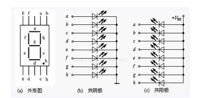
The nixie tube shown in the figure has 8 display strokes "a,b,c,d,e,f,g,h". There are 10 pins up and down, and the middle pins above and below are common poles. The common pin is the cathode, which is the common cathode nixie tube, and the common pin is the anode, which is the common anode nixie tube. Common cathode and common anode nixie tubes cannot be judged from the appearance. They can be judged by applying 3V voltage to the common pole and any stroke LED pin to light the diode, or by measuring the resistance of a multimeter.
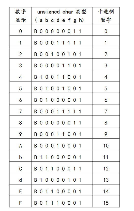
Comparison table between the display number of 1-digit nixie tube with the corresponding luminous LED level of each section:
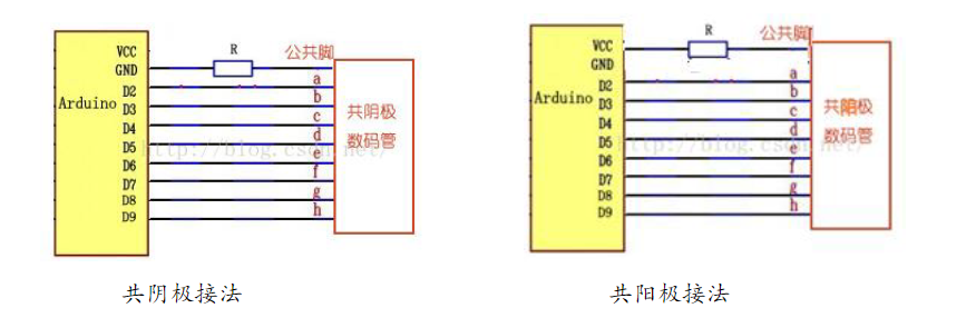
Circuit connection between ArduinoUNO R3 board and 1-bit nixie tube:
2.4} digital tube
According to the number of digits, the encapsulated pins of nixie tubes are also different. However, the light-emitting diodes a, b, c, d, e, f, g and dp of a single nixie tube are connected together, and the common poles are independent of each other. When in use, the display of a single nixie tube is controlled by controlling different bit selection lines (i.e. the common pole of a single nixie tube). Refresh the display at a speed that is difficult for human eyes to distinguish, so as to achieve the effect of simultaneous display of multiple nixie tubes.
The pin distribution of four digit nixie tube is shown in the figure below, in which 1, 2, 3 and 4 represent the common pole of the corresponding digit nixie tube.
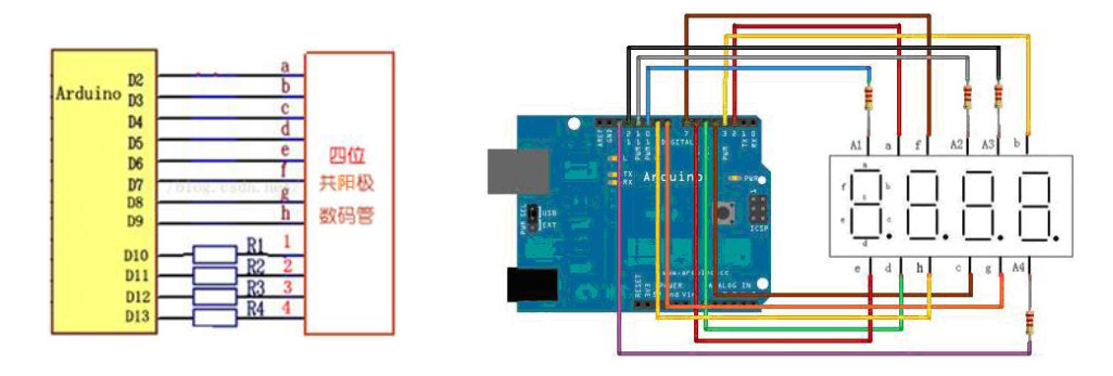
Schematic diagram of four digit nixie tube circuit:
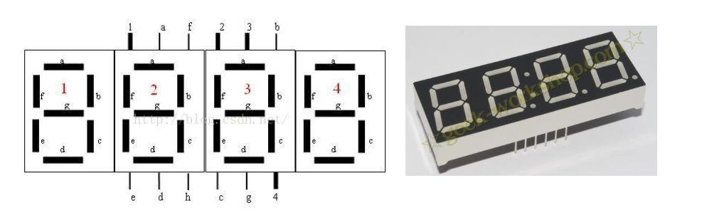
Note: pins 1, 2, 3 and 4 are used to select the digital bits to be processed (common cathode type, low level effective; common anode, high level effective), which is the common pole of this digit. For example, if the digital output level is 1, select 1.
After selecting the number, the operation of abcdefgh each LED is the same as that of a digital tube.
5.3 experimental contents
1. Experimental circuit construction
The common pin of the common anode nixie tube is connected in series with a current limiting resistor connected to VCC, and abcdefgh each pin is connected to Arduino digital D2-D9 interface in sequence.
2.1 digit nixie tube display experiment
Step 1: digital tube abcdefgh pin test
The common pin of 1-bit nixie tube is connected to 3.5V power supply (or grounding), and the other pins are grounded with DuPont line (or 3.5V power supply). Judge and identify the tube sequence of abcdefgh according to the light (off) of LED segment.
Step 2: 1-bit digital display control program preparation:
// Program controlled nixie tube display
int digitPin= 2; //Pin D2 is connected to pin A of nixie tube
void setup() {
    for(int x=0; x<=7; x++)
    pinMode(digitPin+x, OUTPUT);//Set D2~D9 pins as output
}
void loop() {
    for (int x=0; x<16; x++) {
        // 0-9,A-F digital displayDigital(x) are displayed in sequence every 1 second;
        //Call displayDigit() to display the number function
        delay(1000); //Wait 1 second
    }
}
//Custom function, nixie tube display number
void displayDigital(unsigned intdigit) {
    //Define a two-dimensional array to store the abcdefgh value of each number
    unsigned charabcdefgh[][8] = {
    {0,0,0,0,0,0,1,1},//0
    {1,0,0,1,1,1,1,1},//1
    {0,0,1,0,0,1,0,1},//2
    {0,0,0,0,1,1,0,1},//3
    {1,0,0,1,1,0,0,1},//4
    {0,1,0,0,1,0,0,1},//5
    {0,1,0,0,0,0,0,1},//6
    {0,0,0,1,1,1,1,1},//7
    {0,0,0,0,0,0,1,1},//8
    {0,0,0,1,1,0,0,1},//9
    {0,0,0,1,0,0,0,1},//A
    {1,1,0,0,0,0,0,1},//b
    {0,1,1,0,0,0,1,1},//C
    {1,0,0,0,0,1,0,1},//d
    {0,1,1,0,0,0,0,1},//E
    {0,1,1,1,0,0,0,1}//F};
    if ( digit >= 16 ) return;
    for (unsigned intx=0; x<8; x++){
        digitalWrite( digitPin+ x, abcdefgh[digit][x] );
    }
}
// The nixie tube displays a number from 0 to 9, a to f every other second
Step 3: nixie tube display test
3.4-digit digital display control
Step 1: function test of 4-bit nixie tube pin
Connect the 1, 2, 3 and 4 common pins of the 4-bit nixie tube to the 3.5V power supply (or grounding) respectively, and the other pins are grounded with the DuPont line (or 3.5V power supply). Judge and identify the abcdefgh tube sequence of the display bit number controlled by the common pin according to the light (off) of the LED segment.
Step 2: connect the 4-digit nixie tube drive circuit
According to the pin sequence of the four digit nixie tube, the pins a, B, C, D, e, F, G and H are respectively connected to the digital pins D2, D3, D4, D5, D6, D7, D8 and D9 of the Arduino UNO R3 board. The four digital bits 1, 2, 3 and 4 pins of the nixie tube are respectively connected in series with 220 Ω current limiting resistance, and the other end of the resistance is respectively connected with the digital pins D10, D11, D12 and D13 of the development board.
Note: there are many circuit connections. Check whether they are correct before power on and test. Do not overlap incorrectly!
Step 3: write 4-digit nixie tube control program
// 4-digit nixie tube display example program
int digitalPin= 2; //D2 pin is connected to a pin of nixie tube, and D3 is connected to b D9 with h
int weiPin= 10; // First digit PIN interface
void setup() {
    for(int x=0; x<4; x++) {
        pinMode(weiPin+x, OUTPUT); //Set each common pin interface as output
        digitalWrite(weiPin+x, HIGH);//Common pin high level,
    }
    for(int x=0; x<8; x++) {
        pinMode(digitalPin+x, OUTPUT); //Set the led pin interface of each section as output
    }
}
void loop() {
    display(1, 3);//Call the function to display the first digit 3
    display(2, 2);//Call the function to display the second digit 2
    display(3, 1);//Call the function to display the third digit 1
    display(4, 0);//Call the function to display the fourth digit 0
}
// Define digital display function of nixie tube
void displayDigital(unsigned intdigit) {
    unsigned char abcdefgh[][8] = {//Define an array to store the values of abcdefgh each segment of different numbers
    {0,0,0,0,0,0,1,1},//0
    {1,0,0,1,1,1,1,1},//1
    {0,0,1,0,0,1,0,1},//2
    {0,0,0,0,1,1,0,1},//3
    {1,0,0,1,1,0,0,1},//4
    {0,1,0,0,1,0,0,1},//5
    {0,1,0,0,0,0,0,1},//6
    {0,0,0,1,1,1,1,1},//7
    {0,0,0,0,0,0,1,1},//8
    {0,0,0,1,1,0,0,1},//9
    {0,0,0,1,0,0,0,1},//A
    {1,1,0,0,0,0,0,1},//b
    {0,1,1,0,0,0,1,1},//C
    {1,0,0,0,0,1,0,1},//d
    {0,1,1,0,0,0,0,1},//E
    {0,1,1,1,0,0,0,1},//F
    {1,1,1,1,1,1,1,0},//DOT = 16
    {1,1,1,1,1,1,0,1},//MINUS= 17
    {1,1,1,1,1,1,1,1} //BLANK =18}
    if ( digit > 18)return;
    for (unsigned intx=0; x<8; x++)
    digitalWrite( digitalPin+ x, abcdefgh[digit][x] );
}
//Specifies the bit to display the given numeric function
void display(unsigned intwei, unsigned intdigit) {
    const intBLANK 18;
    for(int x=0; x<=3; x++) {
        digitalWrite(weiPin + x,LOW);// Digital bit pin set low
    }
        displayDigital(BLANK); //Call the function to close all display fields
        digitalWrite(weiPin +wei-1 , HIGH);//Select the bit display pin and set it to high level
        delay(1);
        displayDigital(digit);//Calling function bit display numeric field
        delay(1000);//Refers to the digital display time of positioning
}
Step 4: the function test changes the time parameters of the delay(ms) function. When they are 500ms, 100ms, 10ms and 1ms respectively, observe the difference between the display results.
4. Program expansion task: according to the above example, write a program to realize an accumulation counter or a subtraction counter.
int digitalPin= 2;
int weiPin= 10;
int count = -1;
void setup() {
  for(int x=0; x<4; x++) {
    pinMode(weiPin+x, OUTPUT);
    digitalWrite(weiPin+x, HIGH);
  }
  for(int x=0; x<8; x++) {
      pinMode(digitalPin+x, OUTPUT);
  }
}
void loop() {
  count++;
  if(count<10){
    display(4,count);
     delay(1000);
    }else if(count<100){
      for(int i=0;i<50;i++){
      display(3,count/10);
      delay(10);
      display(4,count%10);
      delay(10);
      }}else if(count<1000){
        for(int i=0;i<50;i++){
      display(2,count/100);
      delay(20/3);
      display(3,count/10%10);
      delay(20/3);
      display(4,count%10);
      delay(20/3);
      }
   }
}
void displayDigital(unsigned int digit) {
    unsigned char abcdefgh[][8] = {//Define an array to store the values of abcdefgh each segment of different numbers
      {0,0,0,0,0,0,1,1},//0
      {1,0,0,1,1,1,1,1},//1
      {0,0,1,0,0,1,0,1},//2
      {0,0,0,0,1,1,0,1},//3
      {1,0,0,1,1,0,0,1},//4
      {0,1,0,0,1,0,0,1},//5
      {0,1,0,0,0,0,0,1},//6
      {0,0,0,1,1,1,1,1},//7
      {0,0,0,0,0,0,0,1},//8
      {0,0,0,1,1,0,0,1},//9
      {0,0,0,1,0,0,0,1},//A
      {1,1,0,0,0,0,0,1},//b
      {0,1,1,0,0,0,1,1},//C
      {1,0,0,0,0,1,0,1},//d
      {0,1,1,0,0,0,0,1},//E
      {0,1,1,1,0,0,0,1},//F
      {1,1,1,1,1,1,1,0},//DOT = 16
      {1,1,1,1,1,1,0,1},//MINUS= 17
      {1,1,1,1,1,1,1,1} //BLANK =18
      };
      if(digit > 18)return;
      for (unsigned int x=0; x<8; x++)
      digitalWrite( digitalPin+ x, abcdefgh[digit][x] );
      }
      //Specifies the bit to display the given numeric function
void display(unsigned int wei, unsigned int digit) {
  const int BLANK=18;
  for(int x=0; x<=3; x++) {
    digitalWrite(weiPin + x,LOW);// The digital bit pin is set to low level
    }
    displayDigital(BLANK);    //Call the function to close all display fields
    digitalWrite(weiPin +wei-1 , HIGH);//Select bit display pin
    displayDigital(digit);//Calling function bit display numeric field
}
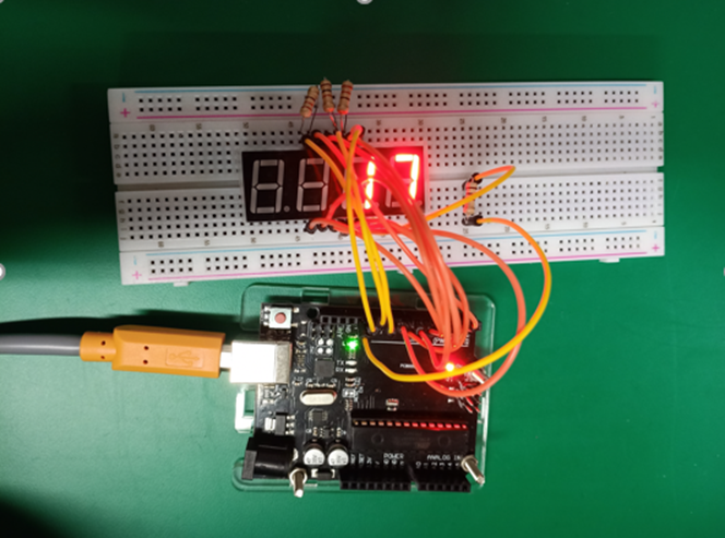
5.4 experimental results
Conclusion: Experiment 1 judges and identifies the tube sequence of abcdefgh according to the light (off) of LED segment. The result of Experiment 2 shows 0 1 2 3 in digital order. Experiment 3, realize the function of timer, which can time.
Reflection: firstly, through this experiment, I am familiar with and master the function of 1-bit nixie tube module; Familiar with the function of 4-digit nixie tube module; 4-bit digital timing display function programming and the application of various functions. Secondly, experiment 1 judges and identifies the tube sequence of abcdefgh according to the light (off) of LED segment. The result of Experiment 2 shows 0 1 2 3 in digital order. Experiment 3, realize the function of timer, which can time. Finally, I also encountered some problems in this experiment. I hope to learn more, be more proficient and make persistent efforts in the future.
Works:
5.5 thinking questions
1. If you use a nixie tube to make a dice to choose a number, how to realize it?
2. How to realize the simultaneous display of 4 digits? Why?
3. If you use a 4-bit nixie tube to complete a minute and second timer, how to realize it on the basis of the existing sample program?