This is the content of "Principles and Interface Technology of Microcomputer" in the course design of the school. I have written some drawbacks, but basically realized the operation function. I will record it temporarily for future review, which is also for your reference.
Defects:
1. Only fixed length input (32 bits corresponding to 00000000 -- FFFFFF)
2. For example, an input of 6 (hexadecimal) can only resemble an input of 00000006
3. Only 0-9 inputs from 0-F are considered, and neither A-F nor A-F are considered.
I have no time to modify it for now, I may write it later
Experimental environment:
1. I debugged Windows 7 on a virtual machine. The cpu displayed in TD debugging is 80486, but this experiment requires 8086 (16 bits). This does not affect, because the 80486 instruction set is forward compatible as long as we write 8086 instructions.
The reason for this is that 80486 already has a new instruction set that allows 32-bit operations directly.
2.... No more >==<!
Design ideas:
Input:
Input, because INT 21 (01H) is called for input, and the function call can only enter one character at a time, and the data stored in AL is its ASCII value, so the input value must first be converted to real data, while adding a loop to complete the input of fixed-length data.
Operation:
Since only 16-bit data can be computed at one time in the 8086 system of 16-bit registers, when we need to perform 32-bit operations, consider segmenting. The result data of each segmentation (DX:AX) is placed in the corresponding memory address (labeled HH, HL, LH, LL).Take 32-bit data DX:AX as an example. Data is divided into high (H) and low (L). Segment Multiplication can be divided into L-L,L-H,H-L,H-H Multiplication (L, H represent high-bit and low-bit data of 32-bit data), where each multiplied value is placed in DX:AX.In L-L, L-L->AX does not need to be considered because it is the lowest bit of the product and MUL directives do not overflow; in the sum of L-L->DX and L-H->AX and H-L->AX, consideration needs to be given to the higher bit situation, the state of the flag register can be stacked using PUSHF, and ADC directives can be used in the higher bit; L-H->DX and H-L->DX and H-H->AXIn addition, both high-bit and low-bit carry values need to be considered, as before; H-H->DX is the highest bit of the product and only low-bit carry needs to be considered.
Output:
When outputting, consider the data after the operation and the output data, that is, the data after the operation is the true value of the product, and the output data is the ASCII value corresponding to the character.At the same time, in order to consider aesthetics, the leading 0 considers to remove it, and judgment jump statement can be achieved.The specific implementation is to determine whether the extracted BX is 0 or not, 0 means that the data does not need to be output, and the program jumps to the next address processing; when the extracted data may have a starting data of 0100/0A11 and a non-starting data of 0100/0A11.That is, the first 0 is not output, but the other 0 is true and needs to be output except the first 0 is not output.Consider designing a flag implementation, this design is implemented with SI, the initial value is 0H, when a true value is output, its value becomes 01H, then the SI and the value to be output are determined simultaneously. When the output value is 0 and SI is 01H, the data is true and needs to be output.
Code:
//mul.asm
DATA        SEGMENT
            BUF1 DB 0DH,0AH,'PLEASE INPUT NUM_1(00000000-99999999):',0DH,0AH,'$'
            BUF2 DB 0DH,0AH,'PLEASE INPUT NUM_2(00000000-99999999):',0DH,0AH,'$'
            BUF3 DB 0DH,0AH,'THE RESULT IS:',0DH,0AH,'$'
            ;Made into any input
            NUM1        DW        2 DUP(?)
            NUM2        DW        2 DUP(?)
            HL            DW        2 DUP(?)
            HH            DW        2 DUP(?)
            LH            DW        2 DUP(?)
            LL            DW        2 DUP(?)
            SUM            DW        4 DUP(?)
DATA        ENDS

CODE        SEGMENT
MAIN        PROC    NEAR
            ASSUME    CS:CODE,DS:DATA
START:
IN_TIPS:
            MOV        BX,DATA
            MOV        DS,BX
IN_1:
            LEA        DX,BUF1
            MOV        AH,09H
            INT        21H
            LEA        BX,NUM1
            CALL    INPUT
IN_2:
            LEA        DX,BUF2
            MOV        AH,09H
            INT        21H
            LEA        BX,NUM2
            ;ADD        BX,3
            CALL    INPUT
;TAKEMUL
            CALL    TAKEMUL
;OUTPUT
            CALL    OUTPUT
;END
            MOV        AH,4CH
            INT        21H
            RET
MAIN        ENDP

INPUT        PROC    NEAR
            MOV        DX,2
INNUM:
            ;1(5)->Input Number
            MOV        AH,01H
            INT        21H
            SUB        AL,30H
            MOV        CL,4
            SHL        AL,CL
            MOV        CL,AL
            ;2(6)->Input Number
            MOV        AH,01H
            INT        21H
            SUB        AL,30H
            ADD        CL,AL
            PUSH    CX
            ;3(7)->Input Number
            MOV        AH,01H
            INT        21H
            SUB        AL,30H
            MOV        CL,4
            SHL        AL,CL
            MOV        CH,AL
            ;4(8)->Input Number
            MOV        AH,01H
            INT        21H
            SUB        AL,30H
            ADD        CH,AL
            MOV        AL,CH
            ;SEND To MEMORY
            POP        CX
            MOV        AH,CL
            MOV        [BX],AX
            ADD        BX,2
            DEC        DX
            JNZ        INNUM
            RET
INPUT        ENDP

TAKEMUL        PROC    NEAR
            LEA        SI,NUM1
            LEA        DI,NUM2
H_L:        ;<<16
            MOV        AX,[SI]
            ADD        DI,2
            MUL        WORD PTR[DI]
            LEA        BX,HL
            MOV        [BX],DX
            ADD        BX,2;WORD
            MOV        [BX],AX
            ADD        BX,2
H_H:        ;<<32
            MOV        AX,[SI]
            SUB        DI,2
            MUL        WORD PTR[DI]
            LEA        BX,HH
            MOV        [BX],DX
            ADD        BX,2
            MOV        [BX],AX
            ADD        BX,2
L_H:        ;<<16
            ADD        SI,2
            MOV        AX,[SI]
            MUL        WORD PTR[DI]
            LEA        BX,LH
            MOV        [BX],DX
            ADD        BX,2
            MOV        [BX],AX
            ADD        BX,2
L_L:        ;<<0
            MOV        AX,[SI]
            ADD        DI,2
            MUL        WORD PTR[DI]
            LEA        BX,LL
            MOV        [BX],DX
            ADD        BX,2
            MOV        [BX],AX
            ADD        BX,2
TAKE:
            ;L-L:
            ;LL->AX:32 position X32 Lowest bits of bitwise operation data
            LEA        DI,LL
            ADD        DI,2
            MOV        AX,[DI]
            LEA        BX,SUM
            MOV        [BX],AX
            ADD        BX,2
            ;LL->DX:LL->DX + LH->AX + HL->AX
            LEA        DI,LL
            MOV        AX,[DI]
            MOV        [BX],AX
            ;ADD        BX,2
            ;HL+LH
            ;HL->AX+LH->AX
            LEA        DI,HL
            ADD        DI,2
            MOV        AX,[DI]
            LEA        DI,LH
            ADD        DI,2
            ADD        AX,[DI]
            PUSHF
            ADD        AX,[BX];LL->DX
            MOV        [BX],AX
            ADD        BX,2
            ;HL->DX+LH->DX (CF)
            LEA        DI,HL
            MOV        AX,[DI]
            LEA        DI,LH
            POPF
            ADC        AX,[DI]
            PUSHF
            MOV        [BX],AX
            ;HH(CF)
            ;HH->AX
            LEA        DI,HH
            ADD        DI,2
            MOV        AX,[DI]
            POPF
            ADC        AX,[BX];HL->DX+LH->DX
            MOV        [BX],AX
            ADD        BX,2
            ;HH->DX
            LEA        DI,HH
            MOV        AX,[DI]
            ADC        AX,0H
            MOV        [BX],AX
            ADD        BX,2
            RET
TAKEMUL        ENDP

OUTPUT        PROC    NEAR
            LEA        DX,BUF3
            MOV        AH,09H
            INT        21H
            LEA        DI,SUM
            ADD        DI,7
            MOV        CX,8
            MOV        SI,0H;RE_COMPARE
ADJUST:
            MOV        BL,[DI]
            MOV        BH,BL
            AND        BX,0F00FH
            PUSH    CX
            CMP        BX,0H
            JE        ZERO
            MOV        CL,4
            SHR        BH,CL
            MOV        DL,BH
            CALL    COMPARE
            MOV        DL,BL
            CALL    COMPARE
ZERO:
            DEC        DI
            POP        CX
            LOOP    ADJUST
            RET
OUTPUT        ENDP

COMPARE        PROC    NEAR
            CMP        DL,0AH
            JAE        OUT_ENG;JNB
            CMP        DL,00H
            JE        RE_COMPARE
            JA        OUT_NUM
            JMP        COMPARE_END
RE_COMPARE:
            CMP        SI,0H
            JE        COMPARE_END
            JNE        OUT_NUM
OUT_ENG:
            ADD        DL,37H;ACSII->A-0AH
            MOV        AH,02H
            INT        21H
            MOV        SI,01H
            JMP        COMPARE_END
OUT_NUM:
            ADD        DL,30H
            MOV        AH,02H
            INT        21H
            MOV        SI,01H
COMPARE_END:
            RET
COMPARE        ENDP

CODE        ENDS
            END        START
Since the explanation in the analysis is clear and the code naming is relatively familiar, there are no comments (very few) and then a debug Blog under the TD tool will be uploaded. I think this will be more useful!!!
Let's take two screenshots ~~
Description: Input and output are all 16-digit numbers, why 16-digit?Because the registers contain hexadecimal, I am not foolish, just output directly, why to convert.Ha Ha Ha Ha Ha Ha@@, smart!!!
Verification Note: Validation data is computed using a calculator.
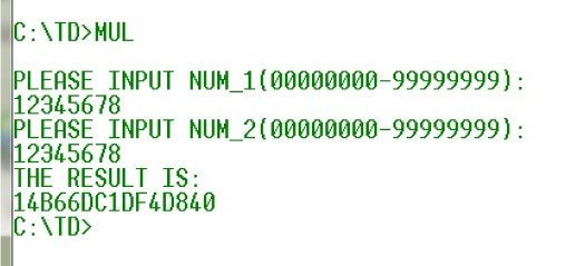
Verify 1:12345678H * 12345678H = 14B 66DC 1DF4 D840H
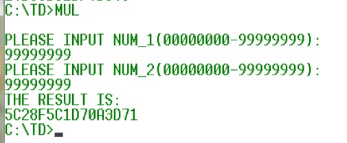
Validation 2:99999999H * 999999H = 5C28 F5C1 D70A 3D71H
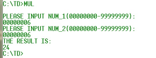
Verify 3:6H * 6H = 24H
Well ~ o(**) o, that's basically it!Welcome to Reference. If you have written more completely, please leave a message to provide a link.