technological process
A classic flow chart
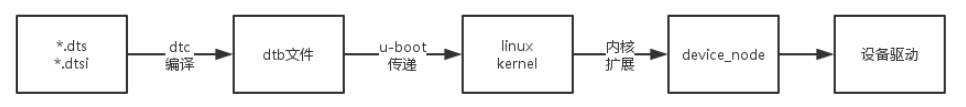
dtc compiled commands
make dtbs
dtsi: an SOC may have different boards / machines, refining common parts or common parts of multiple machines into dtsi (common refinement), the difference part is put in dts, then The corresponding of include in dts dtsi file is enough. If there are different settings on the same node, the configuration in dts will be overwritten dtsi configuration (last effective)
dtc: dtc is a tool for compiling dts. You can install the dtc tool through the instruction apt get install device tree compiler on Ubuntu system. The dtc tool is already included in the kernel source code scripts/dtc path
dtb: dtb(Device Tree Blob). dtb files will be obtained after dts is compiled by dtc. dtb is loaded into the kernel through Bootloader bootloader (such as U-Boot). Therefore, Bootloader needs to support the device tree; Kernel also needs the support of adding device tree
catalogue
Some not in the mainline kernel may have their own directory, others will generally be in the default directory
Default directory of DT file: arch/*/boot/dts, where * represents architecture arm/arm64//mips/riscv/x86, etc. for example, the device tree related to stm32mp157a-dk1 is under arch/arm/boot/dts Directory:
# Push backwards
stm32mp157a-dk1.dts	# The unique description of dk1 board is less than that of stm32mp157c-dk2, such as touch screen, Bluetooth, WiFi, etc
	- stm32mp157.dtsi	# gpu and DSI (display interface) description
		- stm32mp153.dtsi	# CPU1, arm PMU, can description
			- stm32mp151.dtsi	# Cpu0, arm PMU, PSCI, INTC, GPIO / timer and other peripherals, clocks, booster, mlahb
				- dt-bindings/interrupt-controller/arm-gic.h
				- dt-bindings/clock/stm32mp1-clks.h
				- dt-bindings/reset/stm32mp1-resets.h
	- stm32mp15-pinctrl.dtsi	# PINMUX description
		- dt-bindings/pinctrl/stm32-pinfunc.h
	- stm32mp15xxac-pinctrl.dtsi	# pinctrl, gpioa~gpioi, gpioz description
	- stm32mp15xx-dkx.dtsi	# Common hardware description of dk1/dk2 board
		- dt-bindings/gpio/gpio.h
		- dt-bindings/mfd/st,stpmic1.h
format
Devicetree node is defined with node name and cell address (optional), and braces mark the beginning and end of node definition They can have a label in front of them Basic format of node:
[label:] node-name[@unit-address] {
  [properties definitions]
  [child nodes]
};

# [] optional

# [label:] label, 1 ~ 31 characters (letters, numbers, underscores), Do not start with a number
# Create a reference by adding the & symbol before the label, such as interrupt affinity = < & cpu0 >, < & CPU1 >;

# Previously defined nodes / labels / attributes may be deleted
# /delete-node/ node-name;
# /delete-node/ &label;
# /delete-property/ property-name;

# Common types of properties
# text string: double quotation marks, such as compatible = "arm,cortex-a7";
# cells, angle brackets, u32 type, 64bit value is represented by two 32-bit cell s, such as clock frequency = < 0x00000001 0x00000000 >;
# binary data, square brackets, such as local MAC address = [00 00 12 34 56 78]; Equivalent [000012345678]

# Is phandle the abbreviation of properties handle? Value is a method of referring to another node in the device tree, which is simply understood as a handle

# Reference the full path of a node, enclosed in curly braces
# interrupt-parent = < &{/soc/interrupt-controller@40000} >;

# Tags may also appear before or after any component of the attribute value, or between cells of a cell array, or between bytes of a byte string
# reg = reglabel: <0 sizelabel: 0x1000000>;
# prop = [ab cd ef byte4: 00 ff fe];
# str = start: "string value" end: ;

# C style (/ *... * /) and C + + style (/ /) annotations are supported

# Nodes in the device tree can be uniquely identified by specifying a full path from the root node to all descendant nodes to the desired node
# E.g. / cpus/cpu@0

# compatible = "fsl,mpc8641", "ns16550";
# In this example, the operating system will first try to find a device driver that supports fsl, mpc8641
# If the driver is not found, it will try to find a driver that supports the more general ns16550 device type
extract
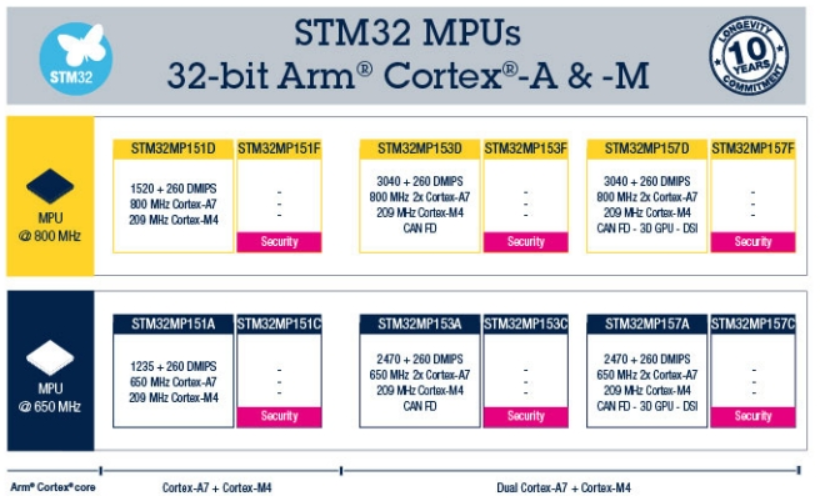
Taking STM32MP157 as an example, the product series of STM32 MPU is as follows
SOC common part extracted:
-
STM32MP157/153 has two Cortex-A7 and stm32mp151 has one Cortex-A7. Therefore, a common Cortex-A7 and all public peripherals can be extracted and made into stm32mp151 Dtsi file, which has the most content
-
STM32MP157/153 has an A7 and CANFD more than 151. The Cortex-A7 and public peripherals (such as CANFD) can be extracted and made into stm32mp153 Dtsi, there are 157 / 153 in this, but 151 doesn't
-
STM32MP157 has more 3D GPU-DSI than 153, so the extra GPU and dtsi form STM32MP157 Dtsi, this one is unique to 157
Extract the common part of the board (dk1 and dk2):
- stm32mp15xx-dkx.dtsi
- The description of DK1 constitutes stm32mp157a-dk1 DTS and DK2 (more Bluetooth / WiFi/DSI, etc.) constitute stm32mp157c-dk2 dts
describe
Explain some common device tree syntax according to the example comments
/* ==============================================================================
* stm32mp157x-dk1.dts
* ============================================================================*/
/dts-v1/; // DTS that identifies the file as version 1. DTS without this tag will be regarded as version 0 by dtc
#include "stm32mp157.dtsi" // Similar to C language, expand
#include "stm32mp15-pinctrl.dtsi"
#include "stm32mp15xxac-pinctrl.dtsi"
#include "stm32mp15xx-dkx.dtsi"
/ { // Each dts or dtsi file consists of a root node '/ {};' form
// Model specifies the manufacturer and equipment model. The recommended format is "manufacturer, model"
model = "STMicroelectronics STM32MP157A-DK1 Discovery Board";
// compatible specifies the system name, including a string in the form of "manufacturer, model" to avoid namespace conflicts
compatible = "st,stm32mp157a-dk1", "st,stm32mp157";
aliases { // Alias, lowercase letters / numbers/-
ethernet0 = ðernet0;
serial0 = &uart4;
serial1 = &usart3;
serial2 = &uart7;
};
// chosen, parameters selected or specified at runtime, input and output of console, etc
// Bootargs: specify boot parameters, such as bootargs = "root = / dev / NFS RW nfsroot = 192.168.1.1 console = ttys0115200";
// Stdout path: Specifies the device to boot console output
// Stdin path: Specifies the device to boot console input
chosen {
stdout-path = "serial0:115200n8"; // serial0 is the &uart4, 115200-n-8 above
};
};
/* ==============================================================================
* stm32mp157x-dk1.dts Excerpt
* ============================================================================*/
/ {
// The word length occupied by absolute addresses such as base address and chip selection number, unit u32, 64bit, system 2?
#address-cells = <1>;
// The word length occupied by the length, unit U32, is 1 for 32bit system and 2 for 64bit system?
#size-cells = <1>;
cpus {
#address-cells = <1>;
// The size cells of cpus should be 0. If the size is not required in the child node attribute, press 0,1 for the CPU address
#size-cells = <0>;
cpu0: cpu@0 {
compatible = "arm,cortex-a7";
clock-frequency = <650000000>; //650MHz
device_type = "cpu";
// The first value of the reg attribute must include [unit address], that is cpu@0 0 in
reg = <0>;
};
};
...
};
/* ==============================================================================
* stm32mp157xx-dkx.dtsi Excerpt
* ============================================================================*/
/ {
memory@c0000000 {
device_type = "memory";
//The starting address is 0xc00000000, the size is 0x20000000(512MB), and the maximum memory is 1GB
reg = <0xc0000000 0x20000000>;
};
};
//Some examples of peripherals
//spi
spi1: spi@44004000 {
#address-cells = <1>;
#size-cells = <0>;
compatible = "st,stm32h7-spi";
reg = <0x44004000 0x400>;
interrupts = <GIC_SPI 35 IRQ_TYPE_LEVEL_HIGH>;
clocks = <&rcc SPI1_K>;
resets = <&rcc SPI1_R>;
dmas = <&dmamux1 37 0x400 0x05>,
<&dmamux1 38 0x400 0x05>;
dma-names = "rx", "tx";
status = "disabled";
};
//spi usage example
//CS gpios indicates the GPIO list used for chip selection, such as CS gpios = < &gpioz 3 0 >;
//dmas: by default, DMA is specified for all SPI instances
//&spi1 {
// pinctrl-names = "default", "sleep";
// pinctrl-0 = <&spi1_ pins_ a>; // Pin configuration
// pinctrl-1 = <&spi1_sleep_pins_a>;
// status = "okay";
//
// foo@0 {
// compatible = "spi-foo"; // The name of the SPI device driver
// reg = <0>; /* CS #0 */ // Index of gpio chips associated with spi devices
// spi-max-frequency = <10000000>; // SPI maximum clock speed Hz
// };
//};
//adc
//IIO (Industrial I/O) is a subsystem for analog-to-digital converter (ADC), digital to analog converter (DAC) and various types of sensors.
//Used by ADC Linux driver, which registers relevant information in IIO framework
//Resolution setting assigned resolution bits = < 12 >
adc: adc@48003000 { //soc configuration, do not modify
compatible = "st,stm32mp1-adc-core";
reg = <0x48003000 0x400>; //Starting address 0x48003000, size 0x400(1KB)
interrupts = <GIC_SPI 18 IRQ_TYPE_LEVEL_HIGH>,
<GIC_SPI 90 IRQ_TYPE_LEVEL_HIGH>;
clocks = <&rcc ADC12>, <&rcc ADC12_K>;
clock-names = "bus", "adc";
interrupt-controller;
st,syscfg = <&syscfg>;
#interrupt-cells = <1>;
#address-cells = <1>;
#size-cells = <0>;
status = "disabled"; //These are the public resources of adc1 and adc2
adc1: adc@0 {
compatible = "st,stm32mp1-adc";
#io-channel-cells = <1>;
reg = <0x0>;
interrupt-parent = <&adc>;
interrupts = <0>;
dmas = <&dmamux1 9 0x400 0x01>;
dma-names = "rx";
status = "disabled";
};
adc2: adc@100 {
compatible = "st,stm32mp1-adc";
#io-channel-cells = <1>;
reg = <0x100>;
interrupt-parent = <&adc>;
interrupts = <1>;
dmas = <&dmamux1 10 0x400 0x01>;
dma-names = "rx";
status = "disabled";
};
};
&adc { //Board level configuration
pinctrl-names = "default";
pinctrl-0 = <&adc12_ain_pins_a>, <&adc12_usb_cc_pins_a>; //Pin used for configuration
vdd-supply = <&vdd>;
vdda-supply = <&vdd>;
vref-supply = <&vrefbuf>;
status = "disabled";
adc1: adc@0 {
/*
* Type-C USB_PWR_CC1 & USB_PWR_CC2 on in18 & in19.
* Use at least 5 * RC time, e.g. 5 * (Rp + Rd) * C:
* 5 * (56 + 47kOhms) * 5pF => 2.5us.
* Use arbitrary margin here (e.g. 5us).
*/
st,min-sample-time-nsecs = <5000>; // Minimum sampling time, 5us
/* AIN connector, USB Type-C CC1 & CC2 */
st,adc-channels = <0 1 6 13 18 19>; //adc channel, see stm32mp15 pinctrl dtsi
status = "okay"; //Enable adc1
};
adc2: adc@100 {
/* AIN connector, USB Type-C CC1 & CC2 */
st,adc-channels = <0 1 2 6 18 19>;
st,min-sample-time-nsecs = <5000>;
status = "okay"; //Enable adc2
};
};
//canfd
m_can1: can@4400e000 {
compatible = "bosch,m_can"; //Bosch's M_CAN controller
// message_ram address 0x44011000, size 0x1400(5KB)
reg = <0x4400e000 0x400>, <0x44011000 0x1400>;
reg-names = "m_can", "message_ram";
interrupts = <GIC_SPI 19 IRQ_TYPE_LEVEL_HIGH>,
<GIC_SPI 21 IRQ_TYPE_LEVEL_HIGH>;
interrupt-names = "int0", "int1";
clocks = <&rcc CK_HSE>, <&rcc FDCAN_K>;
clock-names = "hclk", "cclk";
bosch,mram-cfg = <0x0 0 0 32 0 0 2 2>;
status = "disabled";
};
m_can2: can@4400f000 {
compatible = "bosch,m_can";
reg = <0x4400f000 0x400>, <0x44011000 0x2800>; //10KB
reg-names = "m_can", "message_ram";
interrupts = <GIC_SPI 20 IRQ_TYPE_LEVEL_HIGH>,
<GIC_SPI 22 IRQ_TYPE_LEVEL_HIGH>;
interrupt-names = "int0", "int1";
clocks = <&rcc CK_HSE>, <&rcc FDCAN_K>;
clock-names = "hclk", "cclk";
bosch,mram-cfg = <0x1400 0 0 32 0 0 2 2>;
status = "disabled";
};
&m_can1 { //Usage examples
pinctrl-names = "default", "sleep"; /* configure pinctrl modes for m_can1 */
pinctrl-0 = <&m_can1_pins_a>; /* configure m_can1_pins_a as default pinctrl configuration for m_can1 */
pinctrl-1 = <&m_can1_sleep_pins_a>; /* configure m_can1_sleep_pins_a as sleep pinctrl configuration for m_can1 */
status = "okay"; /* enable m_can1 */
};
//eth
//Address bits: Specifies the number of bits in the MAC address. If not specified, it defaults to 48, such as address bits = < 48 >;
//Local MAC address, which specifies the MAC address assigned to the network device described by the node containing this attribute, such as local MAC address = [00 00 12 34 56 78];
//MAC address: Specifies the MAC address used by the startup program last time. If it is different from local Mac, use this value, such as MAC address = [01 02 03 04 05 06];
//Max frame size, which specifies the maximum packet length (in bytes) that the physical interface can send and receive, such as Max frame size = < 1518 >;
//PHY connection type: Specifies the interface type between Ethernet device and physical layer (PHY) device, such as PHY connection type = "MII";
//https://wiki.stmicroelectronics.cn/stm32mpu/wiki/Ethernet_device_tree_configuration
//3.3.5 RGMII,ETH _ There is 25MHz on CLK (no PHY crystal) and CLK125 from PHY (reference clock (standard rgmii clock name) is provided by RCC SoC internal clock)
ethernet0: ethernet@5800a000 {
compatible = "st,stm32mp1-dwmac", "snps,dwmac-4.20a";
reg = <0x5800a000 0x2000>; //Starting address 0x5800a000, size 0x2000(8KB)
reg-names = "stmmaceth";
interrupts-extended = <&intc GIC_SPI 61 IRQ_TYPE_LEVEL_HIGH>;
interrupt-names = "macirq";
clock-names = "stmmaceth",
"mac-clk-tx",
"mac-clk-rx",
"eth-ck",
"ethstp";
clocks = <&rcc ETHMAC>,
<&rcc ETHTX>,
<&rcc ETHRX>,
<&rcc ETHCK_K>,
<&rcc ETHSTP>;
st,syscon = <&syscfg 0x4>;
snps,mixed-burst;
snps,pbl = <2>;
snps,en-tx-lpi-clockgating;
snps,axi-config = <&stmmac_axi_config_0>;
snps,tso;
status = "disabled";
};
ðernet0 {
status = "okay"; //Status OK, start Ethernet
pinctrl-0 = <ðernet0_rgmii_pins_a>; //See pinmux mapping (TX/RX/SMI interface) below
pinctrl-1 = <ðernet0_rgmii_sleep_pins_a>; //Let rgmii sleep on all pins
pinctrl-names = "default", "sleep";
phy-mode = "rgmii-id"; // rgmii, id 0
max-speed = <1000>; // Max speed: Specifies the maximum speed supported by the device (Mbit/s)
phy-handle = <&phy0>; // PHY handle: specifies a reference to a node that represents a physical layer (PHY) device connected to this Ethernet device
mdio0 {
#address-cells = <1>;
#size-cells = <0>;
compatible = "snps,dwmac-mdio"; //drivers/net/ethernet/stmicro/stmmac/stmmac_ platform. c. MDIO always releases
phy0: ethernet-phy@0 {
reg = <0>;
};
};
};
ethernet0_rgmii_pins_a: rgmii-0 { //And the pins of the schematic are aligned
pins1 {
pinmux = <STM32_PINMUX('G', 5, AF11)>, /* ETH_RGMII_CLK125 */
<STM32_PINMUX('G', 4, AF11)>, /* ETH_RGMII_GTX_CLK */
<STM32_PINMUX('G', 13, AF11)>, /* ETH_RGMII_TXD0 */
<STM32_PINMUX('G', 14, AF11)>, /* ETH_RGMII_TXD1 */
<STM32_PINMUX('C', 2, AF11)>, /* ETH_RGMII_TXD2 */
<STM32_PINMUX('E', 2, AF11)>, /* ETH_RGMII_TXD3 */
<STM32_PINMUX('B', 11, AF11)>, /* ETH_RGMII_TX_CTL */
<STM32_PINMUX('C', 1, AF11)>; /* ETH_MDC */
bias-disable;
drive-push-pull;
slew-rate = <2>;
};
pins2 {
pinmux = <STM32_PINMUX('A', 2, AF11)>; /* ETH_MDIO */
bias-disable;
drive-push-pull;
slew-rate = <0>;
};
pins3 {
pinmux = <STM32_PINMUX('C', 4, AF11)>, /* ETH_RGMII_RXD0 */
<STM32_PINMUX('C', 5, AF11)>, /* ETH_RGMII_RXD1 */
<STM32_PINMUX('B', 0, AF11)>, /* ETH_RGMII_RXD2 */
<STM32_PINMUX('B', 1, AF11)>, /* ETH_RGMII_RXD3 */
<STM32_PINMUX('A', 1, AF11)>, /* ETH_RGMII_RX_CLK */
<STM32_PINMUX('A', 7, AF11)>; /* ETH_RGMII_RX_CTL */
bias-disable;
};
};
ethernet0_rgmii_sleep_pins_a: rgmii-sleep-0 { // Let rgmii sleep on all pins
pins1 {
pinmux = <STM32_PINMUX('G', 5, ANALOG)>, /* ETH_RGMII_CLK125 */
<STM32_PINMUX('G', 4, ANALOG)>, /* ETH_RGMII_GTX_CLK */
<STM32_PINMUX('G', 13, ANALOG)>, /* ETH_RGMII_TXD0 */
<STM32_PINMUX('G', 14, ANALOG)>, /* ETH_RGMII_TXD1 */
<STM32_PINMUX('C', 2, ANALOG)>, /* ETH_RGMII_TXD2 */
<STM32_PINMUX('E', 2, ANALOG)>, /* ETH_RGMII_TXD3 */
<STM32_PINMUX('B', 11, ANALOG)>, /* ETH_RGMII_TX_CTL */
<STM32_PINMUX('A', 2, ANALOG)>, /* ETH_MDIO */
<STM32_PINMUX('C', 1, ANALOG)>, /* ETH_MDC */
<STM32_PINMUX('C', 4, ANALOG)>, /* ETH_RGMII_RXD0 */
<STM32_PINMUX('C', 5, ANALOG)>, /* ETH_RGMII_RXD1 */
<STM32_PINMUX('B', 0, ANALOG)>, /* ETH_RGMII_RXD2 */
<STM32_PINMUX('B', 1, ANALOG)>, /* ETH_RGMII_RXD3 */
<STM32_PINMUX('A', 1, ANALOG)>, /* ETH_RGMII_RX_CLK */
<STM32_PINMUX('A', 7, ANALOG)>; /* ETH_RGMII_RX_CTL */
};
};
The value of compatible is matched with the program in the driver, such as compatible = "SNPs, dwmac MDIO" in mdio0;, In drivers/net/ethernet/stmicro/stmmac/stmmac_platform.c inside
/**
 * stmmac_dt_phy - parse device-tree driver parameters to allocate PHY resources
 * @plat: driver data platform structure
 * @np: device tree node
 * @dev: device pointer
 * Description:
 * The mdio bus will be allocated in case of a phy transceiver is on board;
 * it will be NULL if the fixed-link is configured.
 * If there is the "snps,dwmac-mdio" sub-node the mdio will be allocated
 * in any case (for DSA, mdio must be registered even if fixed-link).
 * The table below sums the supported configurations:
 *	-------------------------------
 *	snps,phy-addr	|     Y
 *	-------------------------------
 *	phy-handle	|     Y
 *	-------------------------------
 *	fixed-link	|     N
 *	-------------------------------
 *	snps,dwmac-mdio	|
 *	  even if	|     Y
 *	fixed-link	|
 *	-------------------------------
 *
 * It returns 0 in case of success otherwise -ENODEV.
 */
static int stmmac_dt_phy(struct plat_stmmacenet_data *plat,
			 struct device_node *np, struct device *dev)
{
	bool mdio = !of_phy_is_fixed_link(np);
	static const struct of_device_id need_mdio_ids[] = {
		{ .compatible = "snps,dwc-qos-ethernet-4.10" },
		{},
	};

	if (of_match_node(need_mdio_ids, np)) {
		plat->mdio_node = of_get_child_by_name(np, "mdio");
	} else {
		/**
		 * If snps,dwmac-mdio is passed from DT, always register
		 * the MDIO
		 */
		for_each_child_of_node(np, plat->mdio_node) {
			if (of_device_is_compatible(plat->mdio_node,
						    "snps,dwmac-mdio"))
				break;
		}
	}

	if (plat->mdio_node) {
		dev_dbg(dev, "Found MDIO subnode\n");
		mdio = true;
	}

	if (mdio) {
		plat->mdio_bus_data =
			devm_kzalloc(dev, sizeof(struct stmmac_mdio_bus_data),
				     GFP_KERNEL);
		if (!plat->mdio_bus_data)
			return -ENOMEM;

		plat->mdio_bus_data->needs_reset = true;
	}

	return 0;
}
Overall memory mapping
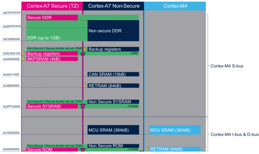
Example of mapping in the device tree
// stm32mp151.dtsi
dma-ranges = <0x00000000 0x38000000 0x10000>,	// RETRAM 64KB mapping
	     <0x10000000 0x10000000 0x60000>,	// MCU SRAM 384KB mapping
	     <0x30000000 0x30000000 0x60000>;
There are also interrupt mapping, etc. omitted here
reference resources
- 6. Devicetree Source (DTS) Format (version 1) — Devicetree Specification v0.3-dirty documentation (devicetree-specification.readthedocs.io)
- Microprocessors - STM32 Arm Cortex 32-bit MPU - STMicroelectronics
- STM32MP157A-DK1 - Discovery kit with STM32MP157A MPU - STMicroelectronics
- STM32MP157C-DK2 - Discovery kit with STM32MP157C MPU - STMicroelectronics
- Device Tree Reference - eLinux.org
- Device tree Linux - elinux org
- Explanation of linux device tree - Overview_ Audio and video developer - CSDN blog
- Detailed explanation of equipment tree - Huaqing vision R & D Center (farlightdev. Com)
- dm00287601-dsi-host-on-stm32f469479-stm32f7x8x9-and-stm32l4r9s9-mcus-stmicroelectronics.pdf
Welcome to scan the two-dimensional code, and pay attention to WeChat official account.