Basic routing policy configuration
Principle overview:
Route policy is widely used. For example, it can specify that the router only publishes some routes that meet specific conditions when publishing routes, only receives some routes that 1 meet specific conditions when receiving routes, only introduces some routes that meet specific conditions when introducing routes, and so on.
Route policy is composed of one or more nodes. Nodes have an or relationship. Each Node has a number, and routing items pass through each Node in the order of Node number from small to large. There can be several if match and apply clauses under each Node to define the matching rules, that is, the conditions that the routing item needs to meet to pass through the current Node. The matching object is some attributes of the routing item, such as routing prefix, Next Hop, Cost, routing priority, etc.: the apply clause is used to specify the processing action.
Each Node of the route policy has a corresponding permit mode or deny mode. If it is in permit mode, when the routing item meets the apply clause of the Node, it will not enter the next Node; If the routing item does not meet all if match clauses of the Node, it will enter the next Node to continue filtering. If it is in deny mode, when the routing item meets all if match clauses of the Node, it will be rejected to pass the filtering of the Node. At this time, the apply clause will not be executed and will not enter the next Node; Otherwise, enter the next Node to continue filtering.
Experimental purpose
Master the basic configuration method of route policy
Master the use of route policy for route filtering
Master how to use route policy to modify OSPF routing attributes
Experiment content:
In this experiment, R2, R3 and R4 are the routers of a company's headquarters, R1 is the partner's router, RIPv2 is run between R1 and R2 and R4, and OSPF is run between R3 and R2 and R4. LoopBack 0, LoopBack 1, LoopBack 2, LoopBack 3 and LoopBack 4 of R1 are respectively used to simulate the four network segments within the partner. The network administrator hopes to configure the routing policy to enable R3 to go to 192.168 1.0/24 network segment and 192.168 The traffic of the 3.0/24 network segment goes to 192.168 via path R3-R2-R1 2.0/24 network segment and 192.168 The traffic of the 4.0/24 network segment passes through the path R3-R4-R1, and the two paths are backup to each other.
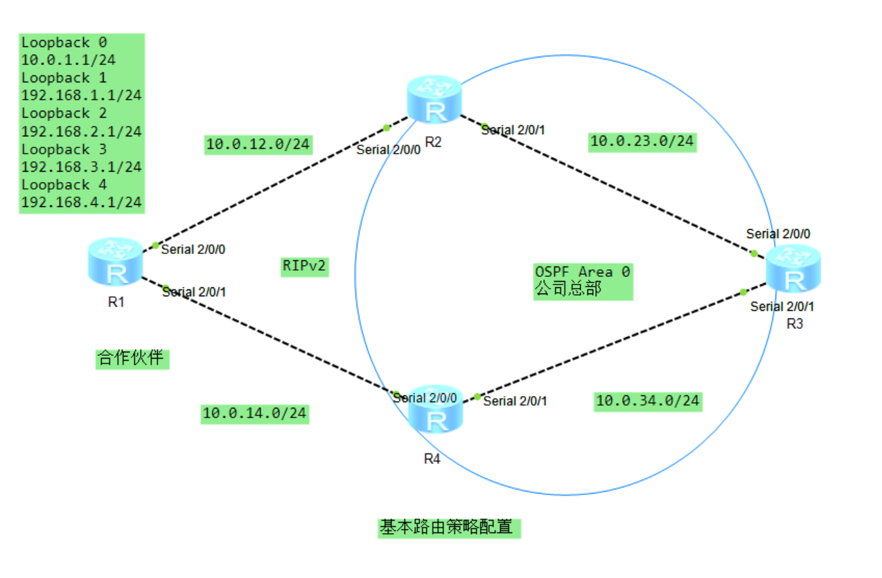
1: Basic configuration of routing device interface:
R1: ((including loopback interface)

#

interface LoopBack0

 ip address 10.0.1.1 255.255.255.255

#

interface LoopBack1

 ip address 192.168.1.1 255.255.255.0

#

interface LoopBack2

 ip address 192.168.2.1 255.255.255.0

#

interface LoopBack3

 ip address 192.168.3.1 255.255.255.0

#

interface LoopBack4

 ip address 192.168.4.1 255.255.255.0

#

interface Serial2/0/0

 link-protocol ppp

 ip address 10.0.12.1 255.255.255.0

#

interface Serial2/0/1

 link-protocol ppp

 ip address 10.0.14.2 255.255.255.0

R2:
#

interface Serial2/0/0

 link-protocol ppp

 ip address 10.0.12.2 255.255.255.0

#

interface Serial2/0/1

 link-protocol ppp

 ip address 10.0.23.2 255.255.255.0

R3:
#

interface Serial2/0/0

 link-protocol ppp

 ip address 10.0.23.1 255.255.255.0

#

interface Serial2/0/1

 link-protocol ppp

 ip address 10.0.34.2 255.255.255.0

R4:
#

interface Serial2/0/0

 link-protocol ppp

 ip address 10.0.14.1 255.255.255.0

#

interface Serial2/0/1

 link-protocol ppp

 ip address 10.0.34.1 255.255.255.0

2: build OSPF and RIP Network:
R1 And R2 and R4 Run between RIPv2,R3 And R2 and R4 Run between OSPF,stay R2 and R4 Admiral RIP Route introduction·reach OSPF In the agreement.

R1:
#

rip 1

 version 2

 network 10.0.0.0

 network 192.168.1.0

 network 192.168.2.0

 network 192.168.3.0

 network 192.168.4.0

R2:

#

ospf 1

 area 0.0.0.0

  network 10.0.23.1 0.0.0.0

#

rip 1

 undo summary

 version 2

 network 10.0.0.0

R3:
#

ospf 1

 area 0.0.0.0

  network 10.0.23.2 0.0.0.0

  network 10.0.34.2 0.0.0.0

R4:

#

ospf 1

 area 0.0.0.0

  network 10.0.34.1 0.0.0.0

#

rip 1

 undo summary

 version 2

 network 10.0.0.0


[R2-ospf-1]import-route rip 1
[R4-ospf-1]import-route rip 1
After configuration, check the IP routing table of R3 to see if R3 has received RIP routing information
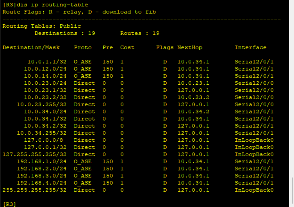
It can be seen that the routing in RIP process has been successfully introduced into OSPF process. By default, the Cost value of the route introduced into OSPF is 1, the Cost Type is Type-2, and the protocol priority value is 150 It can also be seen that routing redundancy occurs due to the introduction of routing on R2 and R4.
For example. From R3 to 192.168 At 1.0/24, the next hop can be R4(10.0.34.1) or R2 (10.0.23.1);
3: Use route policy to filter and modify the routes introduced into the OSPF process
By default, the operation of introducing a route will introduce all routes of the introduced protocol into the target protocol. If you need to filter the imported route information or modify some attributes of the imported route information, you can use route policy.
Now it is required to go from R3 to 192.168 1.0/24 and 192.168 3.0/24, the traffic of these two network segments passes through the path
R3-R2-R1 also requires that the Cost value of the two network segments when the routes are introduced into OSPF on R2 is 20 and the Cost Type is Type-1. On the other hand, in order to achieve routing redundancy, the Cost value of the two routes when introduced into R4 is 30 and the Cost Type is Type-1. In this way, when R3-R2-R1 fails, R3-R4-R1 can be used as the backup path.
In order to meet the above requirements, the following ACL wildcard mask is used for direct matching.
[R2-acl-basic-2000]rule permit source 192.168.1.0 0.0.254.255


[R4-acl-basic-2000]rule permit source 192.168.1.0 0.0.254.255
Create a route policy and 192.168 on R2 1.0/24 and 192.168 When 3.0/24 is introduced into OSPF, Cost is set to 30 and Cost Type is set to Type-1: 192.168 is set on R4 1.0/24 and 192.168 When 3.0/24 is introduced into OSPF, Cost is set to 30 and Cost Type is set to Type-1.
[R2]route-policy import-ospf permit node 5

[R2-route-policy]if-match acl 2000

[R2-route-policy]apply cost 20

[R2-route-policy]apply cost-type type-1


[R4]route-policy import-ospf permit node 5

[R4-route-policy]if-match acl 2000

[R4-route-policy]apply cost 30

[R4-route-policy]apply cost-type type-1
When introducing RIP to OSPF on R2 and R4, route policy is applied
[R2-ospf-1]import rip route-policy import-ospf


[R4-ospf-1]import rip route-policy import-ospf
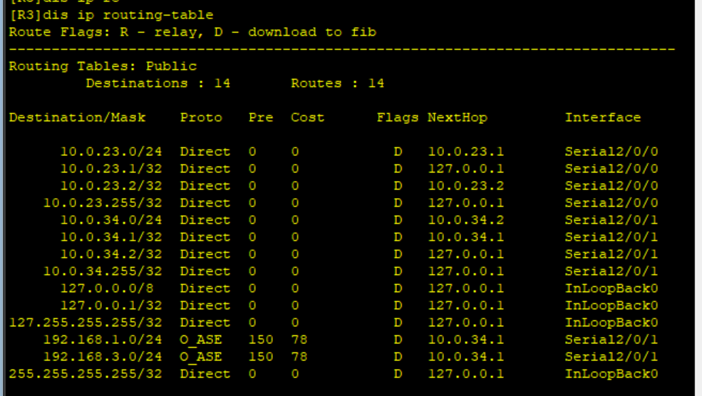
After configuration, view the IP routing table of R3
R3 goes to 192.168 1.0/24 and 192.168 The next hop of 3.0/24 is 10.0 23.1, i.e. S2/0/1 interface on R3 is closed
IntS2/0/1

Shutdown
IntS2/0/1

Undo Shutdown
Now it is required to go from R3 to 192.168 2.0/24 and 192.168 4.0/24 the traffic of the two network segments passes through the path R3-R4-R1. At the same time, it is also required that the Cost value of the routes of the two network segments when introduced into OSPF on R4 is 20
R2:
[R2-acl-basic-2001]rule permit source 192.168.2.0 0.0.254.255


R4:
[R4-acl-basic-2001]rule permit source 192.168.2.0 0.0.254.255
Add new policy nodes on R2 and R4
[R2]route-policy import-ospf permit node 10

[R2-route-policy]if-match acl 2001

[R2-route-policy]apply cost 30

[R2-route-policy]apply cost-type type-2


[R4]route-policy import-ospf permit node 10

[R4-route-policy]if-match acl 2001

[R4-route-policy]apply cost 20

[R4-route-policy]apply cost-type type-2
After configuration, view
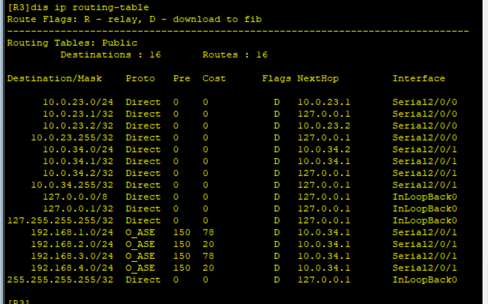
You can see from R3 to 192.168 2.0/24 and 192.168 The flow of 4.0/24 will pass through R3-R4-R1. When the path fails, it will switch to R3-R2-R1.
[R2]route-policy import-ospf permit node 100


[R4]route-policy import-ospf permit node 100
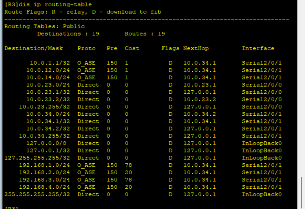
It can be seen that R3 has been able to receive information about 10.0 Routing information of 1.1/32.
R1 and R2 interconnected network segment 10.0 12.0/24 and network segment 10.0 interconnected by R1 and R4 14.0/24 is also introduced into OSPF. Because these two network segments are Internet segments and do not carry services, the company does not want to introduce these two network segments into OSPF, so it is required to filter these two network segments when routing is introduced.
To realize these two requirements, new policy statements need to be added to explicitly refuse to introduce these two Internet segments into OSPF protocol
[R2]ip ip-prefix hedp index 10 permit 10.0.12.0 24

[R2]ip ip-prefix hedp index 20 permit 10.0.14.0 24


[R4]ip ip-prefix hedp index 10 permit 10.0.12.0 24

[R4]ip ip-prefix hedp index 20 permit 10.0.14.0 24


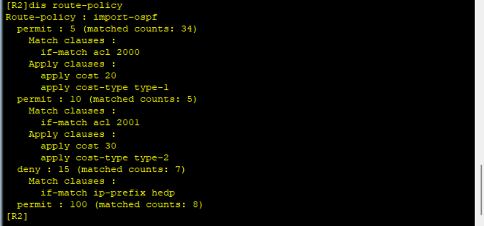
[R2]route-policy import-ospf deny node 15

[R2-route-policy]if-match ip-prefix hedp


[R4]route-policy import-ospf deny node 15

[R4-route-policy]if-match ip-prefix hedp
View the configuration of routing policy on R2
View the IP routing table of R3
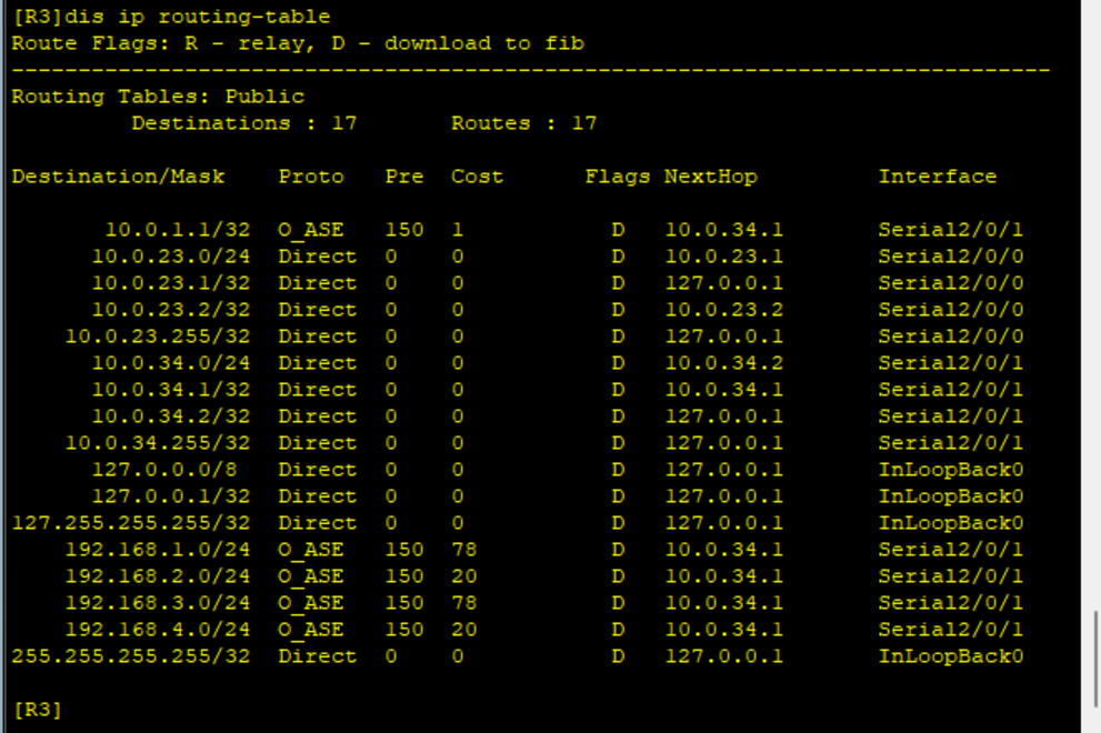
As you can see, about 10.0 12.0/24 and 10.0 The routing information of 14.0/24 has disappeared, while 10.0 1.1/32 still exists, indicating that the needs have been met.