BGP basic experiment
Title Requirements
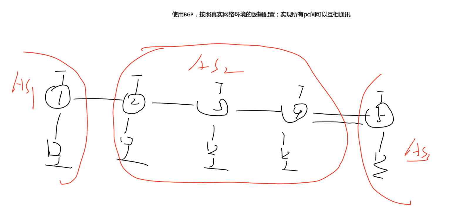
BGP is used and configured according to the logic of the real network environment; All PC s can communicate with each other.
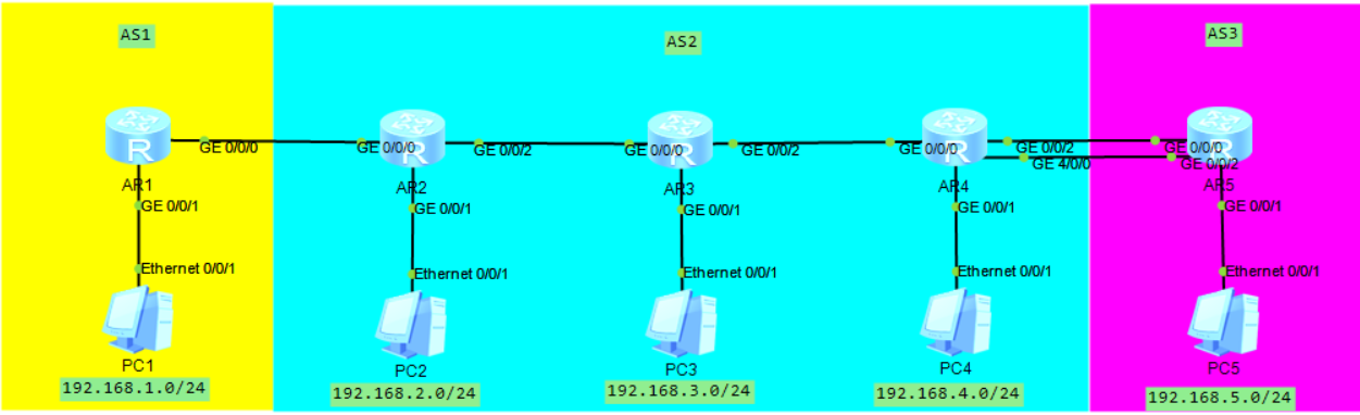
Simulation connection diagram
Experimental steps
1, Configure IP address
For R1
sys
sys r1
int g0/0/0
ip add 12.1.1.1 24
int g0/0/1
ip add 192.168.1.1 24
int lo0
ip add 1.1.1.1 32
For R2
sys
sys r2
int g0/0/0
ip add 12.1.1.2 24
int g0/0/1
ip add 192.168.2.1 24
int g0/0/2
ip add 23.1.1.1 24
int lo0
ip add 2.2.2.2 32
For R3
sys
sys r3
int g0/0/0
ip add 23.1.1.2 24
int g0/0/1
ip add 192.168.3.1 24
int g0/0/2
ip add 34.1.1.1 24
int lo0
ip add 3.3.3.3 32
For R4
sys
sys r4
int g0/0/0
ip add 34.1.1.2 24
int g0/0/1
ip add 192.168.4.1 24
int g0/0/2
ip add 45.1.1.1 24
int g4/0/0
ip add 54.1.1.1 24
int lo0
ip add 4.4.4.4 32
For R5
sys
sys r5
int g0/0/0
ip add 45.1.1.2 24
int g0/0/1
ip add 192.168.5.1 24
int g0/0/2
ip add 54.1.1.2 24
int lo0
ip add 5.5.5.5 32
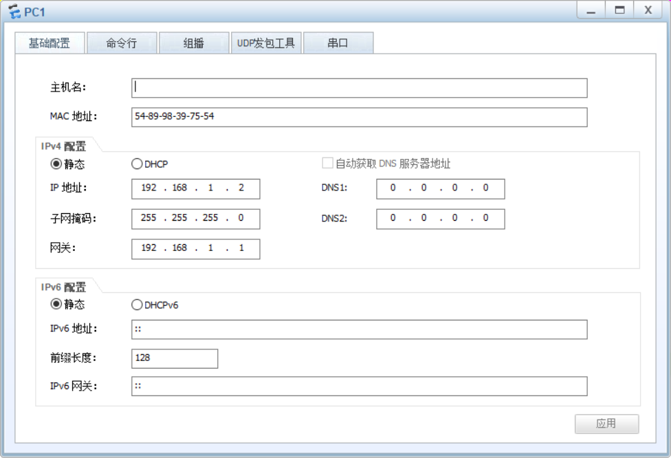
Configure the PC address, taking R1 as an example
2, Complete the internal communication of each AS
Note: the internal structure of AS1 and AS3 is simple. After the IP address is configured, the communication can be realized without declaring ospf
Declare OSPF in AS2
For R2
sys
ospf 1 router-id 2.2.2.2
area 0
network 2.2.2.0 0.0.0.255
network 23.1.1.0 0.0.0.255
network 192.168.2.0 0.0.0.255
For R3
sys
ospf 1 router-id 3.3.3.3
area 0
network 3.3.3.0 0.0.0.255
network 23.1.1.0 0.0.0.255
network 34.1.1.0 0.0.0.255
network 192.168.3.0 0.0.0.255
For R4
sys
ospf 1 router-id 4.4.4.4
area 0
network 4.4.4.0 0.0.0.255
network 34.1.1.0 0.0.0.255
network 192.168.4.0 0.0.0.255
3, Jianlin
1. Neighboring R1 and R2
For R1
bgp 1					 	When starting, you need to define its location AS There is no concept of multiple processes
router-id 1.1.1.1			Recommended configuration RID,And OSPF of RID Consistent configuration rules
peer 12.1.1.2 as-number 2	Establish a neighbor relationship and define the location of peer devices ip Address and location AS number
For R2
bgp 2
router-id 2.2.2.2
peer 12.1.1.1 as-number 1
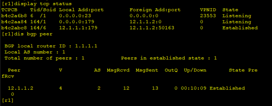
View TCP connection status and BGP neighbor table
2. Establish IBGP neighbors within AS2
Prerequisite: make sure that the Loopback interfaces of R2, R3 and R4 can be routed
Remember: once the loopback address is used as the neighbor address, the source ip address needs to be modified to be the local loopback address;
(1) R2 and R3 establish neighbors
For R2
bgp 2
peer 3.3.3.3 as-number 2			And own 3.3.3.3IP Address routing neighbor,And define each other's AS number
peer 3.3.3.3 connect-interface LoopBack 0	After using the loopback address as the neighbor address,You also need to modify the source ip The address is the local loopback address;
For R3
bgp 2
router-id 3.3.3.3
peer 2.2.2.2 as-number 2
peer 2.2.2.2 connect-interface LoopBack 0
(2) R3 and R4 establish neighbors
For R3
bgp 2
peer 4.4.4.4 as-number 2
peer 4.4.4.4 connect-interface LoopBack 0
For R4
bgp 2
router-id 4.4.4.4
peer 3.3.3.3 as-number 2
peer 3.3.3.3 connect-interface LoopBack 0
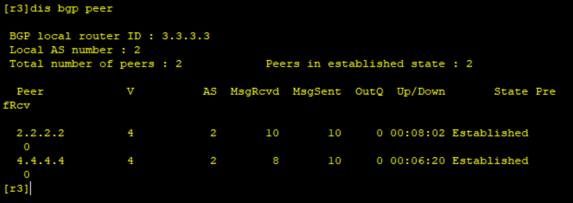
BGP neighbor table of R3:
(3) R4 and R5 establish neighbors
Because there are two links between AR4 and AR5 neighbors, when establishing EBGP neighbors, you need to use loopback to establish neighbors
When using loopback to establish EBGP neighbor, pay attention to whether the loopback of R4 and R5 can communicate normally. If not, the neighbor cannot be established
1) The method of handwritten static routing is used to realize mutual communication
For R4
ip route-static 5.5.5.0 24 45.1.1.2
ip route-static 5.5.5.0 24 54.1.1.2
For R5
ip route-static 4.4.4.0 24 45.1.1.1
ip route-static 4.4.4.0 24 54.1.1.1
2)R4 and R5 establish neighbors
For R4
bgp 2
peer 5.5.5.5 as-number 3
peer 5.5.5.5 connect-interface LoopBack 0
peer 5.5.5.5 ebgp-max-hop 2			Modify neighbors TTL The value is 2
For R5
bgp 3
router-id 5.5.5.5
peer 4.4.4.4 as-number 2
peer 4.4.4.4 connect-interface LoopBack 0
peer 4.4.4.4 ebgp-max-hop 2			Modify neighbors TTL The value is 2
Because between EBGP neighbors, the default TTL value is 1 and IBGP is 255; Theoretically, there is no third router between EBGP neighbors. Two directly connected physical interfaces between two EBGP neighbor routes are used to establish neighbors, so the TTL value is set to 1 by default; However, in reality, the loopback neighbor is used, so the TTL value must be modified to 2
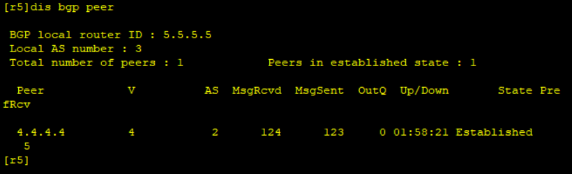
Neighbor table of R5:
4, BGP route announcement
BGP route declaration is used to enable routes between AS regions to learn from each other
In the actual scenario, backbone routes are announced between AS, so you only need to announce the network segment of the user
1. In AS1, for R1
[r1]bgp 1
[r1-bgp]network 192.168.1.0 24
2. In AS2
For R2
[r2]bgp 2
[r2-bgp]network 192.168.2.0 24
For R3
[r3]bgp 2
[r3-bgp]network 192.168.3.0 24
For R4
[r4]bgp 2
[r4-bgp]network 192.168.4.0 24
3. In AS3, for R5
[r5]bgp 2
[r5-bgp]network 192.168.5.0 24
Note: when announcing, the declared entry content must be completely consistent with that in the local routing table;
In BGP, loopback is generally used to establish neighbors, so the loopback address is not announced during route announcement
5, Solve routing problem
1. Question one
Problem: when you check the routing table after announcing the route, you will find that you can't learn the route of AR2 in AR4.
Reason: This is because of the horizontal segmentation of IBGP - routes learned through IBGP neighbors will not be sent to their IBGP neighbor peers
Solution: AR2 needs to establish a separate IBGP neighbor for AR4
For R2
[r2]bgp 2
[r2-bgp]peer 4.4.4.4 as-number 2
[r2-bgp]peer 4.4.4.4 connect-interface LoopBack 0
For R4
[r4]bgp 2
[r4-bgp]peer 2.2.2.2 as-number 2
[r4-bgp]peer 2.2.2.2 connect-interface LoopBack 0
2. Question two
Problem: the routing of R1 and R5 learned on R3 is not good
Reason: AS-BY-AS – when a routing message is transmitted to IBGP neighbors, its attribute is not numbered by default
Solution: when R2 and R4 pass the routing entry to the next neighbor, modify the next hop to the local address
For R2
[r2]bgp 2
[r2-bgp]peer 3.3.3.3 next-hop-local
[r2-bgp]peer 4.4.4.4 next-hop-local
For R4
[r4]bgp 2
[r4-bgp]peer 2.2.2.2 next-hop-local
[r4-bgp]peer 3.3.3.3 next-hop-local
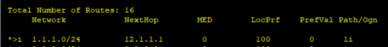
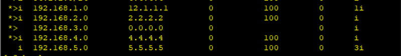
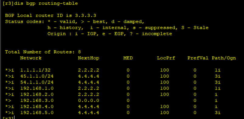
BGP routing table after solving the problem:
6, Testing
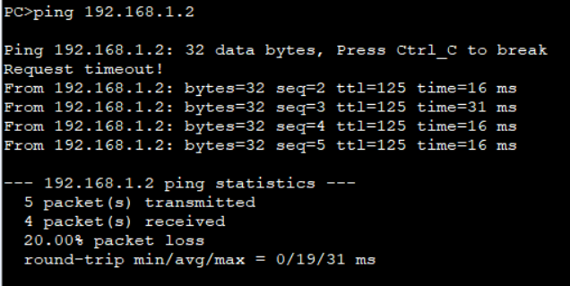
PC1 under AS1 Ping PC2 under as2
R1 in AS1 Ping R5 in AS3
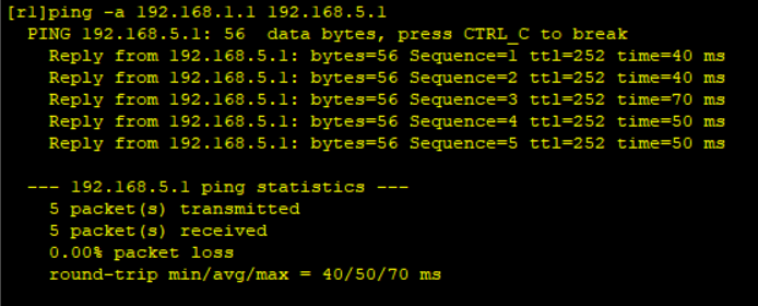
Successful experiment!!!!