BGP: Border Gateway Routing Protocol - Dynamic Routing Protocol
Classless path vector EGP protocol;
AS – autonomous system – standard number 16 digits 0-65535, of which 1-64511 is public and 64512-65535 is private
Extended AS 32-bit binary
IGP protocol pursues: 1. Acyclic (better routing) 2. Fast convergence 3. Less resource consumption
The pursuit of EGP agreement:
1. Strong controllability (administrators can easily conduct policy interference routing)
2, Reliability (a large number of routing entries need to be exchanged between BGP protocol devices, but periodic updates cannot be selected to occupy link resources, so trigger updates can only be carried out; in order to save costs, non direct connections must be established - unicast neighbors) - TCP based operation - three handshakes, four disconnects, four reliable transmission mechanisms - TCP can only work based on unicast
Unicast - IP reachable - IGP dependent BGP hosted on IGP
3. AS-BY-AS takes an AS as AS a hop;
2, BGP features:
1) Classless path vector - upgraded version of distance vector - AS – BY – AS
2) Sending all information using unicast updates; Working based on TCP 179 port
3) Incremental update – only trigger no cycle
4) It has rich attributes to replace the metrics in IGP for routing - multiple parameter control protocol
5) A strong strategy can be implemented for traffic in and out - controllability
6) The default is not used for load balancing - only one optimal path is generated through various routing rules
7) BGP supports authentication and aggregation (summary)
3, BGP packet
Open is only responsible for the establishment of neighbor relationship, and can receive and send once normally; Carry route ID;
Keeplive keeps alive for 1min to query whether the neighbor relationship exists; Actually keep the TCP session alive; hold time is 3min by default
Update carries the routing entry target network number + various attributes
The Notification sends and receives the wrong data;
4, Working process of BGP
1. IP reachability based on IGP;
2. Unicast transmission between neighbors establishes TCP session channel through three handshakes
3. Use open message to establish neighbor relationship. Generally, it can be sent and received once; Generate neighbor table;
4. Use update to share routing information, which carries the target network number + various attributes
5. Generate BGP table - load all routing information sent and received locally
6. Then load the optimal path in the BGP table into the routing table;
7. After the convergence is completed, only keep the keeplive cycle alive
8. All BGP packets are based on TCP sessions to ensure the reliability of transmission
9. If an error message appears, Notification will be used for alarm
10. If the structure changes suddenly, use update to trigger the update
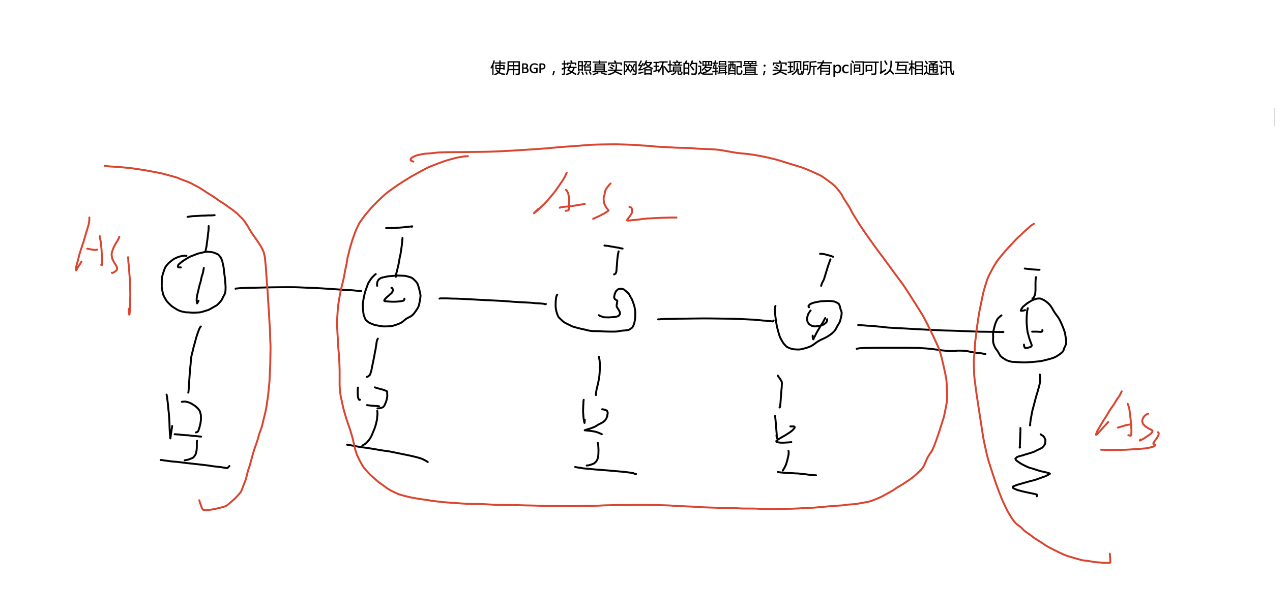
Test requirements:

Experimental topology:

Step 1:
Configure interface loopback IP address:
[r1]int g0/0/0
[r1-GigabitEthernet0/0/0]ip add 12.1.1.1 24
[r1-GigabitEthernet0/0/0]int g0/0/1
[r1-GigabitEthernet0/0/1]ip add 192.168.1.254 24
[r1]int l0
[r1-LoopBack0]ip add 1.1.1.1 24

[r2]int g0/0/0
[r2-GigabitEthernet0/0/0]ip add 12.1.1.2 24
[r2-GigabitEthernet0/0/0]int g0/0/1
[r2-GigabitEthernet0/0/1]ip add 23.1.1.1 24
[r2-GigabitEthernet0/0/1]int g0/0/2
[r2-GigabitEthernet0/0/2]ip add 192.168.2.254 24
[r2]int l0
[r2-LoopBack0]ip add 2.2.2.2 24

R3:
GigabitEthernet0/0/0              23.1.1.2/24
GigabitEthernet0/0/1              34.1.1.1/24
GigabitEthernet0/0/2              192.168.3.254/24
LoopBack0                         3.3.3.3/24

R4:
GigabitEthernet0/0/0              34.1.1.2/24
GigabitEthernet0/0/1              45.1.1.1/24
GigabitEthernet0/0/2              192.168.4.254/24
GigabitEthernet4/0/0              54.1.1.2/24
LoopBack0                         4.4.4.4/24

R5
GigabitEthernet0/0/0              45.1.1.2/24          up         up
GigabitEthernet0/0/1              192.168.5.254/24     up         up
GigabitEthernet0/0/2              54.1.1.1/24          up         up
Test:
Ping R2 on R1, and the rest are the same.

Step 2:
ospf protocol is run inside each AS. BGP is used for interfaces between AS and cannot be declared in ospf.
[r2]ospf 1 router-id 2.2.2.2
[r2-ospf-1]area 0
[r2-ospf-1-area-0.0.0.0]net 23.1.1.1 0.0.0.0
[r2-ospf-1-area-0.0.0.0]net 192.168.2.0 0.0.0.255
[r2-ospf-1-area-0.0.0.0]net 2.2.2.2 0.0.0.0

[r3]ospf 1 router-id 3.3.3.3
[r3-ospf-1]area 0
[r3-ospf-1-area-0.0.0.0]net 23.1.1.2 0.0.0.0
[r3-ospf-1-area-0.0.0.0]network 34.1.1.1 0.0.0.0
[r3-ospf-1-area-0.0.0.0]network 192.168.3.0 0.0.0.255
[r3-ospf-1-area-0.0.0.0]net 3.3.3.3 0.0.0.0

[r4]ospf 1 rou
[r4]ospf 1 router-id 4.4.4.4
[r4-ospf-1]area 0
[r4-ospf-1-area-0.0.0.0]net  192.168.4.0 0.0.0.255
[r4-ospf-1-area-0.0.0.0]net 4.4.4.4 0.0.0.0
[r4-ospf-1-area-0.0.0.0]net 34.1.1.2 0.0.0.0

AS1 And AS2 Use between BGP:
[r1]bgp 1
[r1-bgp]router-id 1.1.1.1
[r1-bgp]peer 12.1.1.2 as-number 2

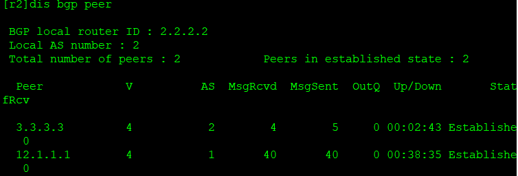
[r2]bgp 2
[r2-bgp]router-id 2.2.2.2
[r2-bgp]peer 12.1.1.1 as-number 1

[r3] bgp 2
[r3-bgp]peer 4.4.4.4 as-number 2
[r3-bgp]peer 4.4.4.4 connect-interface LoopBack 0
[r3-bgp]peer 2.2.2.2 as-number 2
[r3-bgp]peer 2.2.2.2 connect-interface LoopBack 0

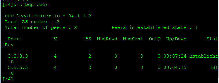
[r4]bgp 2
[r4-bgp]peer 3.3.3.3 as-number 2
[r4-bgp]peer 3.3.3.3 connect-interface LoopBack 0
[r4-bgp]peer 5.5.5.5 as-number 3
[r4-bgp]peer 5.5.5.5 connect-interface LoopBack 0

[r5-LoopBack0]bgp 3
[r5-bgp]peer 4.4.4.4 as-number 2
[r5-bgp]peer 4.4.4.4 connect-interface LoopBack 0
R5:

R4:

R3:

R2:

R1:

Step 3: announce your own user network segment with BGP on R1
[r1]bgp 1
[r1-bgp]network 1.1.1.0 24
BGP routing on R1

View R2:

When looking at R3, we find that the route on R3 is not optimal.
We modify the next clause from R2 to R3
[r2-bgp]peer 3.3.3.3 next-hop-local
After the modification, we found that R3 was the best,

However, it cannot be transmitted to R4 because of the horizontal segmentation mechanism on R4, so we let R2 and R4 establish neighbors
[r2]bgp 2
[r2-bgp]peer 4.4.4.4 as-number 2
[r2-bgp]peer 4.4.4.4 connect-interface LoopBack 0
[r2-bgp]peer 4.4.4.4 next-hop-local

[r4]bgp 2
[r4-bgp]peer 2.2.2.2 as-number 2
[r4-bgp]peer 2.2.2.2 connect-interface LoopBack 0
The same as above on R5, because the relevant configurations have been completed on R2, R3 and R4, you can directly announce the network segment.
Test:
