catalogue
Title and requirements
Investigation module
- Three King Kong: LED, key, nixie tube.
- relay.
- AD.
analysis:
1. Module analysis
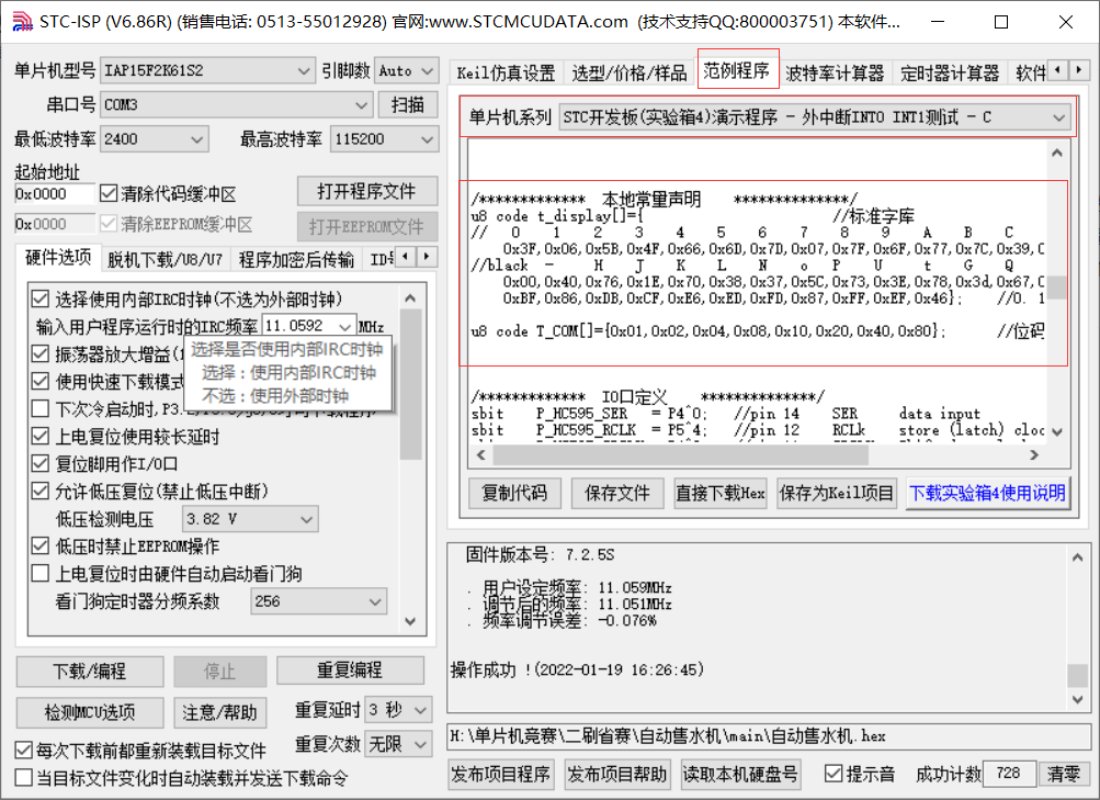
Timer generation: it is realized by burning software STC ISP.
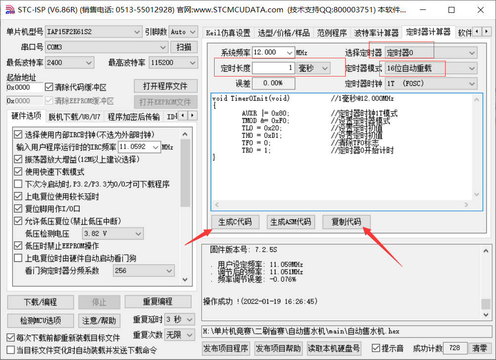
void Timer0Init(void)		//1ms @ 12.000MHz
{
	EA=1;ET0=1;            //certain! certain! certain! To disconnect
	AUXR |= 0x80;		//Timer clock 1T mode
	TMOD &= 0xF0;		//Set timer mode
	TL0 = 0x20;		//Set timing initial value
	TH0 = 0xD1;		//Set timing initial value
	TF0 = 0;		//Clear TF0 flag
	TR0 = 1;		//Timer 0 starts timing
}
Note: be sure to open and interrupt, otherwise the back nixie tube and key will not respond.
Generation of digital tube segment code and bit code table: it is realized by burning software STC ISP.
/*************  Local constant declaration**************/
u8 code t_display[]={                       //Standard font
//   0    1    2    3    4    5    6    7    8    9    A    B    C    D    E    F
    0x3F,0x06,0x5B,0x4F,0x66,0x6D,0x7D,0x07,0x7F,0x6F,0x77,0x7C,0x39,0x5E,0x79,0x71,
//black  -     H    J    K    L    N    o   P    U     t    G    Q    r   M    y
    0x00,0x40,0x76,0x1E,0x70,0x38,0x37,0x5C,0x73,0x3E,0x78,0x3d,0x67,0x50,0x37,0x6e,
    0xBF,0x86,0xDB,0xCF,0xE6,0xED,0xFD,0x87,0xFF,0xEF,0x46};    //0. 1. 2. 3. 4. 5. 6. 7. 8. 9. -1

u8 code T_COM[]={0x01,0x02,0x04,0x08,0x10,0x20,0x40,0x80};      //Bit code
Key
Because only keys S7 and S6 are required, and the title is also clearly required, I use independent keys to realize keys S7 and S6.
Note: the key anti chattering is realized by timer, and 10ms is used for anti chattering.
//Three lines of code for independent keys
void ReadKey()
{
 	ReadData=P3^0xff;
	Trg= ReadData&(ReadData^Cont);
	Cont= ReadData;
}
void dsp_key()
{
	if(key_flag)
	{
		key_flag=0;
		ReadKey();
		switch(Trg)
		{
			case 0x02:			  //s6
			 ....//Key function implementation code
			break;
			case 0x01:			  //s7
			    ....//Key function implementation code
			break;
		}
	}

}
Nixie tube
The dynamic scanning of nixie tube is realized by timer, scanning once every 2ms.
  if(++Smg_count>= 2 )					//2ms scan refresh nixie tube
  {
  	Smg_count=0;
	P2=0xe0;P0=0xff;P2=0x00;				 //Nixie tube blanking
	P2=0xc0;P0=T_COM[i];P2=0x00;    //Bit selection
	P2=0xe0;P0=~t_display[smg_table[i]];P2=0x00;        //Segment selection

	i++;
	if(i>=8)i=0;
  }
LED
Only L1 is used to turn on and off this time, then:
L1 Off: P2 = 0x80;P0 = 0xff; P2 = 0x00;
L1 On: P2 = 0x80;P0 = 0xfe; P2 = 0x00;
relay
Relay on and off
sbit buzzer = P0^6;					  //Buzzer
sbit relay = P0^4;					  //relay

Relay off: P2 = 0xa0;buzzer = 0 ;relay = 0; P2 = 0x00;
Relay on: P2 = 0xa0;buzzer = 0 ;relay = 1; P2 = 0x00;
AD
In addition to the iic code given in the official data package, you also need to write your own code.
//Write the address to be read
void write_adc(unsigned char add)
{
IIC_Start();
IIC_SendByte(0x90);
IIC_WaitAck();
IIC_SendByte(add);
IIC_WaitAck();
IIC_Stop();
}
//read
unsigned char read_adc(unsigned char add)
{
unsigned char temp;
IIC_Start();
IIC_SendByte(0x90);
IIC_WaitAck();
IIC_SendByte(add);
IIC_WaitAck();
IIC_Start();
IIC_SendByte(0x91);
IIC_WaitAck();
temp=IIC_RecByte();
IIC_WaitAck();
IIC_Stop();
return temp;
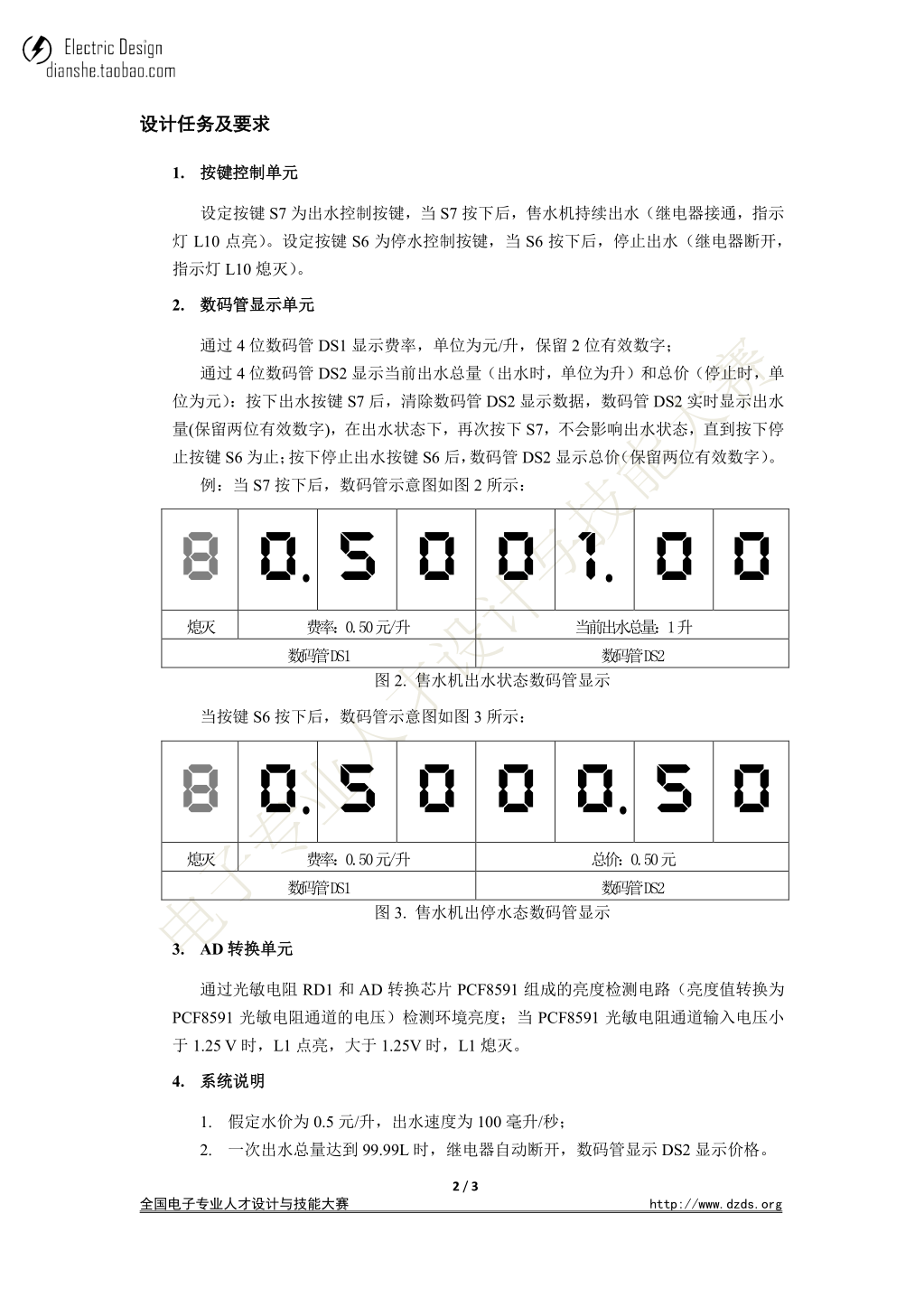
}2. Topic requirement analysis
Question:
S7 is the water outlet control key. After pressing it, the water dispenser continues to discharge water (the relay is connected and the indicator L10 is on).
S6 is the water cut-off control key. Press it to stop water outlet (the relay is disconnected and the indicator L10 is off).
Method: set a flag mode. When mode=0 is the water cut-off mode and mode=1 is the water outlet mode, the relay will turn on and off under the corresponding mode.
problem
It is assumed that the water price is 0.5 yuan / L and the water outlet speed is 100 ml / s.
When the total amount of primary water reaches 99.99L, the relay will be automatically disconnected, and the digital tube will display DS2 and display the price.
Methods: the effluent rate was 100 ml / s, which was converted to 0.01 L / 100 ms.
problem
The ambient brightness is detected by the brightness detection circuit composed of photoresist RD1 and AD conversion chip PCF8591 (the brightness value is converted into the voltage of PCF8591 photoresist channel);
When the input voltage of PCF8591 photoresist channel is less than 1.25 V, L1 is on, and when it is greater than 1.25 V, L1 is off.
Methods: 0~5V is corresponding to 0 ~ 255. We only need to calculate the corresponding value of 0~1.25V, and then judge the IF of the read data, so that we can control and display information.
Note: this requirement needs attention

code implementation
1. Main function
#include<stc15f2k60s2.h>
#include "iic.h"
#define u8 unsigned char
#define u16 unsigned int

sbit buzzer = P0^6;					  //Buzzer
sbit relay = P0^4;					  //relay


/*************  Local constant declaration**************/
u8 code t_display[]={                       //Standard font
//   0    1    2    3    4    5    6    7    8    9    A    B    C    D    E    F
    0x3F,0x06,0x5B,0x4F,0x66,0x6D,0x7D,0x07,0x7F,0x6F,0x77,0x7C,0x39,0x5E,0x79,0x71,
//black  -     H    J    K    L    N    o   P    U     t    G    Q    r   M    y
    0x00,0x40,0x76,0x1E,0x70,0x38,0x37,0x5C,0x73,0x3E,0x78,0x3d,0x67,0x50,0x37,0x6e,
    0xBF,0x86,0xDB,0xCF,0xE6,0xED,0xFD,0x87,0xFF,0xEF,0x46};    //0. 1. 2. 3. 4. 5. 6. 7. 8. 9. -1

u8 code T_COM[]={0x01,0x02,0x04,0x08,0x10,0x20,0x40,0x80};      //Bit code
u8 smg_table[]={16,16,16,16,16,16,16,16};				  //black

u8 ReadData,Trg,Cont;
u16 water_number=0,water_price=0;				  //Water quantity and water fee
u16 Voltage;					   //Voltage
bit mode;				//mode=0 is the water cut-off mode and mode=1 is the water outlet mode
bit key_flag,flag;			//Scan the key mark bit and the water discharge clearing mark
void Close_Peripherals ()
{
  P2 = 0x80;P0 = 0xff; P2 = 0x00;
  P2 = 0xa0;buzzer = 0 ;relay = 0; P2 = 0x00;
}

void Timer0Init(void)		//1ms @ 12.000MHz
{
	EA=1;ET0=1;
	AUXR |= 0x80;		//Timer clock 1T mode
	TMOD &= 0xF0;		//Set timer mode
	TL0 = 0x20;		//Set timing initial value
	TH0 = 0xD1;		//Set timing initial value
	TF0 = 0;		//Clear TF0 flag
	TR0 = 1;		//Timer 0 starts timing
}


void Time_0()  interrupt  1
{
  static u16 Smg_count,key_count,i,water_count;
  if(++Smg_count>= 2 )					//2ms scan refresh nixie tube
  {
  	Smg_count=0;
	P2=0xe0;P0=0xff;P2=0x00;				 //Nixie tube blanking
	P2=0xc0;P0=T_COM[i];P2=0x00;
	P2=0xe0;P0=~t_display[smg_table[i]];P2=0x00;

	i++;
	if(i>=8)i=0;
  }
  if(++key_count>=10){					//10ms scanning independent key
  	 key_count=0;
	 key_flag=1;
  }
  if(mode)
  {
	  if(++water_count>=100)					  //  0.01L/100ms
	  {
	  	water_count=0;
		water_number++;
		if(water_number==9999)
		{
		  P2 = 0xa0;buzzer = 0 ;relay = 0; P2 = 0x00;		 //The relay is disconnected
		  mode=0;
		}
	  }
  }
  else{
  		water_count=0;
		water_price=water_number/2;				//charge for water
  }
}

//Three lines of code for independent keys
void ReadKey()
{
 	ReadData=P3^0xff;
	Trg= ReadData&(ReadData^Cont);
	Cont= ReadData;
}
void dsp_key()
{
	if(key_flag)
	{
		key_flag=0;
		ReadKey();
		switch(Trg)
		{
			case 0x02:			  //s6
			 	P2 = 0xa0;buzzer = 0 ;relay = 0; P2 = 0x00;		 //The relay is disconnected
			  	mode=0;
				flag=1;			//Set the water output clearing flag bit
			break;
			case 0x01:			  //s7
				P2 = 0xa0;buzzer = 0 ;relay = 1; P2 = 0x00;		 //Relay on
			  	mode=1;
			break;
		}
	}

}
void main()
{
	Close_Peripherals();//Turn off peripherals
	Timer0Init();			   //timer initiated
	write_adc(0x01);
	while(1){
		EA=0;
		Voltage=read_adc(0x01);	   //Read the resistance value of the photoresist
		EA=1;
		if((Voltage*5.0/255)<1.25){
		   	  P2=0x80;P0=0xfe;P2=0x00;			 //L1 on
		}else{
		   	  P2=0x80;P0=0xff;P2=0x00;			//L1 off
		}
		dsp_key();
		if(mode)
		{
			if(flag){
				flag=0;
				water_number=0;			//Removal water yield
			}
			//Rate 0.50
		    smg_table[0]=16;
		    smg_table[1]=32;
		    smg_table[2]=5;
		    smg_table[3]=0;
			//Water yield
			smg_table[4]=water_number/1000;
			smg_table[5]=(water_number%1000/100)+32;
			smg_table[6]=water_number%100/10;
			smg_table[7]=water_number%10;
		}else{
			//Rate 0.50
		    smg_table[0]=16;
		    smg_table[1]=32;
		    smg_table[2]=5;
		    smg_table[3]=0;
			//charge for water
			smg_table[4]=water_price/1000;
			smg_table[5]=(water_price%1000/100)+32;
			smg_table[6]=water_price%100/10;
			smg_table[7]=water_price%10;

		}
	}
}
2,I2C(AD)
iic.c
#include "iic.h"


#define DELAY_TIME 5
#define SlaveAddrW 0xA0
#define SlaveAddrR 0xA1

//Bus pin definition
sbit SDA = P2^1;  /* data line */
sbit SCL = P2^0;  /* Clock line */

void IIC_Delay(unsigned char i)
{
    do{_nop_();}
    while(i--);
}
//Bus start condition
void IIC_Start(void)
{
    SDA = 1;
    SCL = 1;
    IIC_Delay(DELAY_TIME);
    SDA = 0;
    IIC_Delay(DELAY_TIME);
    SCL = 0;
}

//Bus stop condition
void IIC_Stop(void)
{
    SDA = 0;
    SCL = 1;
    IIC_Delay(DELAY_TIME);
    SDA = 1;
    IIC_Delay(DELAY_TIME);
}

//Waiting for response
bit IIC_WaitAck(void)
{
    bit ackbit;

    SCL  = 1;
    IIC_Delay(DELAY_TIME);
    ackbit = SDA;
    SCL = 0;
    IIC_Delay(DELAY_TIME);
    return ackbit;
}

//Send data via I2C bus
void IIC_SendByte(unsigned char byt)
{
    unsigned char i;

    for(i=0; i<8; i++)
    {
        SCL  = 0;
        IIC_Delay(DELAY_TIME);
        if(byt & 0x80) SDA  = 1;
        else SDA  = 0;
        IIC_Delay(DELAY_TIME);
        SCL = 1;
        byt <<= 1;
        IIC_Delay(DELAY_TIME);
    }
    SCL  = 0;
}

//Receive data from I2C bus
unsigned char IIC_RecByte(void)
{
    unsigned char i, da;
    for(i=0; i<8; i++)
    {
    	SCL = 1;
	IIC_Delay(DELAY_TIME);
	da <<= 1;
	if(SDA) da |= 1;
	SCL = 0;
	IIC_Delay(DELAY_TIME);
    }
    return da;
}

void write_adc(unsigned char add)
{
	 IIC_Start();
	 IIC_SendByte(0x90);
	 IIC_WaitAck();
	 IIC_SendByte(add);
	 IIC_WaitAck();
	 IIC_Stop();
}

unsigned char read_adc(unsigned char add)
{
	unsigned char temp;
	 IIC_Start();
	 IIC_SendByte(0x90);
	 IIC_WaitAck();
	 IIC_SendByte(add);
	 IIC_WaitAck();
	 IIC_Start();
	 IIC_SendByte(0x91);
	 IIC_WaitAck();
	 temp=IIC_RecByte();
	 IIC_WaitAck();
	 IIC_Stop();
	 return temp;
}
iic.h
#include<stc15f2k60s2.h>
#include "intrins.h"


void IIC_Start(void);
void IIC_Stop(void);
bit IIC_WaitAck(void);
void IIC_SendAck(bit ackbit);
void IIC_SendByte(unsigned char byt);
unsigned char IIC_RecByte(void);

void write_adc(unsigned char add);
unsigned char read_adc(unsigned char add);
Note: Xiaobai just wrote a blog just to make a deeper impression on this topic. At the same time, I hope it can help you a little!!!