1, What is a capture counter?
For example, we want to know the duration of a high-level input to a pin (the signal frequency is actually calculating the duration of the signal input). The timer in stm32 can certainly realize this function.
The timer we just mentioned is not accurate at this time. It should be called counter, because the realization of timing function is actually based on the use of counting function. The timer counts 80M times a second. After prescaled 80, that is, 1m times a second. If the number accounts for 0.1M on the rising edge of the input signal (i.e. high level), it is the high level maintenance of 100ms.
2, So how to configure the timer to achieve such a function?
Take the capture rising edge as an example:
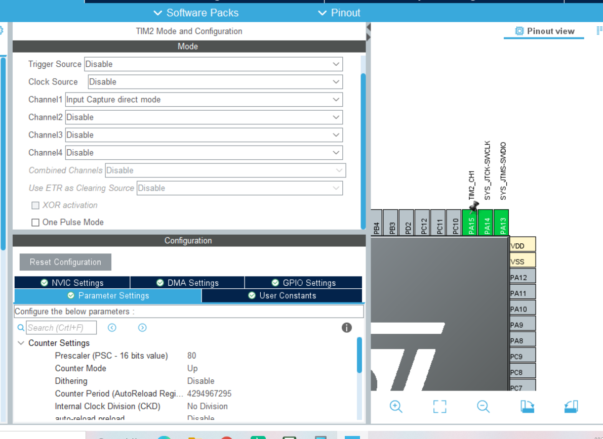
1. Configure timer
See which channel of the timer the signal input pin is in, set this channel of the timer, set the pre division frequency, determine the count value of one second, and the post division frequency shall be as large as possible. The automatic reload value is not set, and the counting mode is upward.
2. Configure this pin as the pull-down input mode
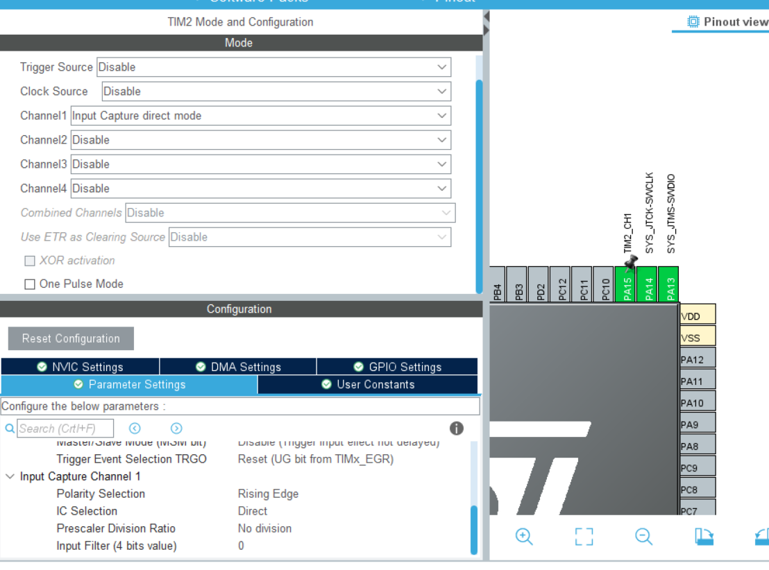
3. Timer input capture settings
It is set to input capture on the rising edge (the interrupt is turned on when the high level ends), and the input capture interrupt is executed when it rises once.
Finally, turn on the interrupt.
4. Input capture interrupt function
Write and read the value of the counter in the interrupt function, and then compare it with the count value within 1s to calculate the existence time of high level. Restart the interrupt (similar to the serial port interrupt accepting function, you need to restart the interrupt every time)
3, Blue Bridge Cup Tim_ Take FRQ routine as an example:
Timer input capture initialization:
TIM_HandleTypeDef htim2;

static void MX_TIM2_Init(void)
{


  TIM_MasterConfigTypeDef sMasterConfig = {0};
  TIM_IC_InitTypeDef sConfigIC = {0};


  htim2.Instance = TIM2;
  htim2.Init.Prescaler = 80;//prescale
  htim2.Init.CounterMode = TIM_COUNTERMODE_UP;//Count up
  htim2.Init.Period = 0xFFFF;//The rear frequency division shall be as large as possible
  htim2.Init.ClockDivision = TIM_CLOCKDIVISION_DIV1;
  htim2.Init.AutoReloadPreload = TIM_AUTORELOAD_PRELOAD_DISABLE;//No automatic reload value
  if (HAL_TIM_IC_Init(&htim2) != HAL_OK)//The variables of the timer structure are substituted into the timer configuration initialization function for initialization
  {
    Error_Handler();
  }
  sMasterConfig.MasterOutputTrigger = TIM_TRGO_RESET;
  sMasterConfig.MasterSlaveMode = TIM_MASTERSLAVEMODE_DISABLE;
  if (HAL_TIMEx_MasterConfigSynchronization(&htim2, &sMasterConfig) != HAL_OK)
  {
    Error_Handler();
  }
	//Input capture interrupt configuration
  sConfigIC.ICPolarity = TIM_INPUTCHANNELPOLARITY_RISING;//Rising edge interrupt (meaning interrupt at the end of high level)
  sConfigIC.ICSelection = TIM_ICSELECTION_DIRECTTI;
  sConfigIC.ICPrescaler = TIM_ICPSC_DIV1;//Break at the end of a rising edge
  sConfigIC.ICFilter = 0;//No filtering is required
  if (HAL_TIM_IC_ConfigChannel(&htim2, &sConfigIC, TIM_CHANNEL_1) != HAL_OK)//The variables in the input capture structure are substituted into the initialization function for initialization
  {
    Error_Handler();
  }

	HAL_TIM_IC_Start_IT(&htim2, TIM_CHANNEL_1);//Open input capture interrupt entry


}
Input capture interrupt execution function:
uint32_t  cc1_value_2 = 0;  									// TIMx_CCR1 µÄÖµ
uint32_t  f40 = 0;

void HAL_TIM_IC_CaptureCallback(TIM_HandleTypeDef *htim)//ÖжϺ¯Êý
{

	cc1_value_2 = __HAL_TIM_GET_COUNTER(&htim2);//Gets the count value of the timer
	__HAL_TIM_SetCounter(&htim2,0);//Zero count
	f40 = 1000000/cc1_value_2;//Calculation frequency

	HAL_TIM_IC_Start_IT(&htim2, TIM_CHANNEL_1);//Reopen the input capture interrupt entry
}
Main function:
int main(void)
{

	char buf[20];

  HAL_Init();

  SystemClock_Config();

  MX_GPIO_Init();
  MX_TIM2_Init();
	LCD_Init();

	LCD_Clear(Blue);
	LCD_SetBackColor(Blue);
	LCD_SetTextColor(White);

	LCD_DisplayStringLine(Line0, (uint8_t *)"                    ");
	LCD_DisplayStringLine(Line1, (uint8_t *)"                    ");
	LCD_DisplayStringLine(Line2, (uint8_t *)"      TIM Test      ");
	LCD_DisplayStringLine(Line3, (uint8_t *)"                    ");
	LCD_DisplayStringLine(Line4, (uint8_t *)"                    ");

	LCD_SetBackColor(White);
	LCD_SetTextColor(Blue);

	LCD_DisplayStringLine(Line5, (uint8_t *)"                    ");
	LCD_DisplayStringLine(Line6, (uint8_t *)"      TIM2 CH1      ");
	LCD_DisplayStringLine(Line7, (uint8_t *)"                    ");
	LCD_DisplayStringLine(Line8, (uint8_t *)"                    ");
	LCD_DisplayStringLine(Line9, (uint8_t *)"                    ");

  while (1)
  {
		sprintf(buf, "  FRQ(R40):%dHz   ",f40);
		LCD_DisplayStringLine(Line8, (uint8_t *)buf);

		HAL_Delay(200);
  }
}
4, Configure with Cubmx:
Perfect operation!