I am snowy fish, an FPGA enthusiast, and my research direction is FPGA architecture exploration.

Pay attention to the official account and pull you into the IC design exchange group.
1, Introduction to LEF
LEF is the abbreviation of Library Exchange Format, which describes the designed library information. The library data includes layer, via, placement site type and macro cell definitions.
1.1 general rules
- Identifiers such as net name and cell name are limited to 2048 characters
- Distance is defined in microns.
- The distance accuracy is controlled by the UNITS statement
- LEF statement with semicolon (;) There must be a space between the last character of the ending. Statement and the semicolon.
1.2 manage LEF documents
All library information required for design can be defined in one LEF file; But doing so will create a large file that is complex and difficult to manage. Therefore, the library information can be divided into two files, one is the "technology" LEF file, and the other is the "cell library" LEF file.
Technology LEF file: the process LEF file contains all process information of the design, such as layout and wiring design rules and layer processing information. A technology LEF file can include any of the following LEF statements:
[VERSION statement]
[BUSBITCHARS statement]
[DIVIDERCHAR statement]
[UNITS statement]
[MANUFACTURINGGRID statement]
[USEMINSPACING statement]
[CLEARANCEMEASURE statement ;]
[PROPERTYDEFINITIONS statement]
[FIXEDMASK ;]
[LAYER (Nonrouting) statement
 | LAYER (Routing) statement] ...
[MAXVIASTACK statement]
[VIA statement] ...
[VIARULE statement] ...
[VIARULE GENERATE statement] ...
[NONDEFAULTRULE statement] ...
[SITE statement] ...
[BEGINEXT statement] ...
[END LIBRARY]
- Cell library LEF file: the cell library LEF file contains macro and standard cell information required for design.
The library LEF file can contain any of the following LEF statements:
[VERSION statement]
[BUSBITCHARS statement]
[DIVIDERCHAR statement]
[VIA statement] ...
[SITE statement]
[MACRO statement
  [PIN statement] ...
  [OBS statement ...] ] ...
[BEGINEXT statement] ...
[END LIBRARY]
Note: when reading the LEF file, you must first read the technology LEF file, because it will be used in the cell library LEF file
technology LEF file defines some library information.
2, Layer (Cut)
Each cut layer is defined by assigning names and design rules. Each cut layer must be defined separately. The layers are defined in the order from low to top. For example:
poly masterslice
cut01 cut
metal1 routing
cut12 cut
metal2 routing
cut23 cut
metal3 routing
This should be easy to understand for friends who have made territory, that is, poly + via + metal1 + via1 + metal2 + via2 + Multi layer superposition, cut layer is actually used to define vias.
Syntax:
LAYER layerName
TYPE CUT ;
[MASK maskNum ;]
[SPACING cutSpacing
   [CENTERTOCENTER]
   [SAMENET]
   [ LAYER secondLayerName [STACK]
    | ADJACENTCUTS {2 | 3 | 4} WITHIN cutWithin [EXCEPTSAMEPGNET]
    | PARALLELOVERLAP
    | AREA cutArea
   ]
;] ...
[SPACINGTABLE ORTHOGONAL
       {WITHIN cutWithin SPACING orthoSpacing} ... ;]
[ARRAYSPACING [LONGARRAY] [WIDTH viaWidth] CUTSPACING cutSpacing
   {ARRAYCUTS arrayCuts SPACING arraySpacing} ... ;]
[WIDTH minWidth ;]
[ENCLOSURE [ABOVE | BELOW] overhang1 overhang2
  [ WIDTH minWidth [EXCEPTEXTRACUT cutWithin]
  | LENGTH minLength]
;] ...
[PREFERENCLOSURE [ABOVE | BELOW] overhang1 overhang2 [WIDTH minWidth] ;] ...
[RESISTANCE resistancePerCut ;]
[PROPERTY propName propVal ;] ...
[ACCURRENTDENSITY {PEAK | AVERAGE | RMS}
  { value
  | FREQUENCY freq_1 freq_2 ... ;
      [CUTAREA cutArea_1 cutArea_2 ... ;]
      TABLEENTRIES
       v_freq_1_cutArea_1 v_freq_1_cutArea_2 ...
       v_freq_2_cutArea_1 v_freq_2_cutArea_2 ...
       ...
  } ;]
[DCCURRENTDENSITY AVERAGE
  { value
  | CUTAREA cutArea_1 cutArea_2 ... ;
      TABLEENTRIES value_1 value_2 ...
  } ;]
[ANTENNAMODEL {OXIDE1 | OXIDE2 | OXIDE3 | OXIDE4} ;] ...
[ANTENNAAREARATIO value ;] ...
[ANTENNADIFFAREARATIO {value | PWL ( ( d1 r1 ) ( d2 r2 ) ...)} ;] ...
[ANTENNACUMAREARATIO value ;] ...
[ANTENNACUMDIFFAREARATIO {value | PWL ( ( d1 r1 ) ( d2 r2 ) ...)} ;] ...
[ANTENNAAREAFACTOR value [DIFFUSEONLY] ;] ...
[ANTENNACUMROUTINGPLUSCUT ;]
[ANTENNAGATEPLUSDIFF plusDiffFactor ;]
[ANTENNAAREAMINUSDIFF minusDiffFactor ;]
[ANTENNAAREADIFFREDUCEPWL
   ( ( diffArea1 diffAreaFactor1 ) ( diffArea2 diffAreaFactor2 ) ...) ; ]
END layerName
example:
LAYER mcon
  TYPE CUT ;

  WIDTH 0.17 ;                # Mcon 1
  SPACING 0.19 ;              # Mcon 2
  ENCLOSURE BELOW 0 0 ;       # Mcon 4
  ENCLOSURE ABOVE 0.03 0.06 ; # Met1 4 / Met1 5

  ANTENNADIFFAREARATIO PWL ( ( 0 3 ) ( 0.0125 3 ) ( 0.0225 3.405 ) ( 22.5 408 ) ) ;
  DCCURRENTDENSITY AVERAGE 0.36 ; # mA per via Iavg_max at Tj = 90oC

END mcon
Since there are many grammars involved here, we won't explain them one by one. When we use them later, we will update them and explain the above examples first.
| sentence | describe |
|---|---|
| WIDTH | Through hole width (square) |
| SPACING | Minimum spacing between through holes |
| ENCLOSURE | BELOW: Specifies the minimum distance between the through hole boundary and the adjacent metal layer boundary BELOW ABOVE: Specifies the minimum distance between the through hole boundary and the upper adjacent metal layer boundary |
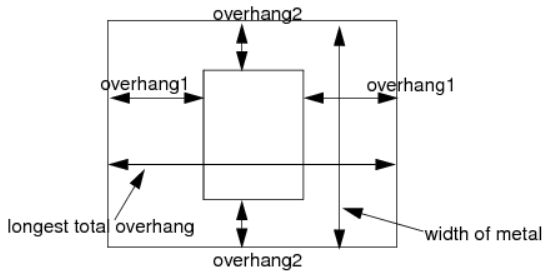
As explained in the figure, the through hole width refers to the width of the middle square (a bit like a rectangle here) in the figure above. Overhaang1 refers to the distance between the left and right sides of the through hole and the metal boundary, and overhaang2 refers to the distance between the upper and lower sides of the through hole and the metal boundary.
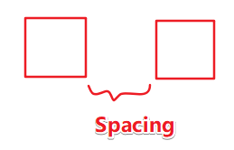
SPACING refers to the SPACING between through holes.
3, Layer(Masterslice or Overlap)
Define MasterSlice or overlay layers in the design. Masterslice layers are usually polysilicon layers, which can only be defined when macro cells have pins on the polysilicon layer.
Syntax:
LAYER layerName
TYPE {MASTERSLICE | OVERLAP} ;
[MASK maskNum ;]
[PROPERTY propName propVal ;] ...
[PROPERTY LEF58_TYPE
   "TYPE [NWELL | PWELL | ABOVEDIEEDGE | BELOWDIEEDGE | DIFFUSION | TRIMPOLY | TRIMMETAL | REGION]
   ];" ;
[PROPERTY LEF58_TRIMMEDMETAL
   "TRIMMEDMETAL metalLayer [MASK maskNum]
   ]; " ;
END layerName| sentence | describe |
|---|---|
| LAYER layerName | Specify the name of the layer. This name will be used later when referencing the layer. |
| TYPE | There are two ways to specify the purpose of the layer -MASTERSLICE: the layer is fixed in the base array. If pins appear in the MASTERSLICE layer, vias must be defined to allow the router to connect those pins to the first wiring layer. The MASTERSLICE layer is not allowed to be used for wiring. A cut layer must be defined between the MASTERSLICE layer and the adjacent wiring layer -Overlay: layer used for line block OVERLAP check. |
example:
LAYER nwell
  TYPE MASTERSLICE ;
  PROPERTY LEF58_TYPE "TYPE NWELL ;" ;
END nwell

LAYER pwell
  TYPE MASTERSLICE ;
  PROPERTY LEF58_TYPE "TYPE PWELL ;" ;
END pwell
- For more technical articles and learning materials, please pay attention to my official account: integrated circuit design course.
- Unified across the platform: [snowy fish]