Entering automotive electronics for two years, I have been doing BSP work, but I have not touched CAN debugging. This opportunity to make a CAN interface for the upper layer, some problems encountered during debugging are recorded below.
1. CAN bus baud rate calculation
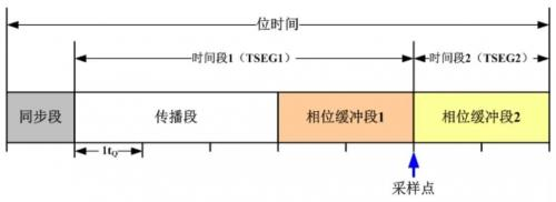
Baud rates can be assigned directly to previously contacted communication protocols, but a sample of a CAN is divided into four time periods.
 Its formula for calculating the baud rate is:
BAUD_RATE_CLOCK/(BAUD_RATE_BRP+1)/(1 +(BAUD_RATE_TSEG1+1)+(BAUD_RATE_TSEG2+1))
To provide a convenient interface for the upper layer, after the clock source is selected, the baud rate configuration is written to death, and a more general sampling point is selected, while the synchronization jump width is left out in a macro-defined way.
	if(baudrate == CAN_BAUD_500K)
	{
		//BAUD_RATE_CLOCK/(BAUD_RATE_BRP+1)/(1 +(BAUD_RATE_TSEG1+1)+(BAUD_RATE_TSEG2+1))
		sMSCANConfig.sBaudRateSetting.SJW = USR_DEF_SJW; //Synchronization jump width, the number of quantum clock cycles in a bit that can be shortened or extended to keep synchronization
    	sMSCANConfig.sBaudRateSetting.BRP = 1; //Baud rate Prescaler
    	sMSCANConfig.sBaudRateSetting.SAMP = BAUD_RATE_SAMP; // 0
    	sMSCANConfig.sBaudRateSetting.TSEG1= 15;  //Bus Timer Register Period 1
    	sMSCANConfig.sBaudRateSetting.TSEG2= 2;  //Bus Timer Register Period 2
	}
	if(baudrate == CAN_BAUD_250K)
	{
		sMSCANConfig.sBaudRateSetting.SJW = USR_DEF_SJW;
    	sMSCANConfig.sBaudRateSetting.BRP = 3;
    	sMSCANConfig.sBaudRateSetting.SAMP = BAUD_RATE_SAMP;
    	sMSCANConfig.sBaudRateSetting.TSEG1= 15;
    	sMSCANConfig.sBaudRateSetting.TSEG2= 2;
	}
	else
	{
		sMSCANConfig.sBaudRateSetting.SJW = USR_DEF_SJW;
    	sMSCANConfig.sBaudRateSetting.BRP = 7;
    	sMSCANConfig.sBaudRateSetting.SAMP = BAUD_RATE_SAMP;
    	sMSCANConfig.sBaudRateSetting.TSEG1= 15;
    	sMSCANConfig.sBaudRateSetting.TSEG2= 2;
	}
2. Received Message Filtering in CAN
The message ID of a CAN can be simply understood as a message filtering token, so a message filtering interface is provided when receiving.General message filtering is composed of ID+MASK.Reading the chip manual, we found that the ID and MSK registers of KEA128 are a bit complex.
KEA128 provides two sets of 32-bit registers for setting ID s and MSK s, each shared by standard frames (11bit) and extended frames (29bit) (more specifically, the chip's MRn bit setting is 0 for the unmatching mask and 1 for the mismatch.This is what I converted in the underlying interface) From the bit distribution of the above registers, you can see the ID position distribution of standard and extended frames.Configuration interfaces must be provided for various frame formats.So here's a function to calculate IDAR and IDMR registers
//Parameter 1 is the frame type, parameter 2 is one of any ID group that needs to be filtered, parameter 3 is the mask, and parameter 4 is the register group ID (0, 1, respectively)
void can_fliter_interface(can_frame_type_t type,uint32_t id_base,uint32_t mask,uint8_t flt_group)
{
	uint32_t code = id_base;
	uint32_t code_high;
	uint32_t code_low;
	uint32_t mask_high;
	uint32_t mask_low;
	if(CAN_STD_FRAME == type)
	{
		//Standard Frame 11 Bit code
		switch(flt_group)
		{
			case 0:
			{
				code = code<<21;
				uIDAR0 = code;
				mask = mask<<21;
				uIDMR0 = ~mask;//Underlying Reverse Code Conversion
			}
			break;
			case 1:
			{
				code = code<<21;
				uIDAR1 = code;
				mask = mask<<21;
				uIDMR1 = ~mask;
			}
			break;
			default:
			break;
		}

	}
	if(CAN_EXT_FRAME == type)
	{
		//Extended Frame 29 Bit code
		switch(flt_group)
		{
			case 0:
			{
				//Take the high 11 bits of code and move to the high 11 bits of 32 bits
				code_high= (code&0x1FFC0000)<<3;
				//Take the lower 18 bits of code and move to 1-19 bits of 32 bits
				code_low = (code&0x3FFFF)<<1;
				uIDAR0 = (code_high|((uint32_t)0x18<<16)|code_low);
				mask_high= (mask&0x01FFC0000)<<3;
				mask_low = (mask&0x3FFFF)<<1;
				uIDMR0 = ~(mask_high|(0x01|(uint32_t)0x10<<16)|mask_low);

			}
			break;
			case 1:
			{
				code_high= (code&0x1FFC0000)<<3;
				code_low = (code&0x3FFFF)<<1;
				uIDAR1 = (code_high|((uint32_t)0x18<<16)|code_low);
				mask_high= (mask&0x01FFC0000)<<3;
				mask_low = (mask&0x3FFFF)<<1;
				uIDMR1 = ~(mask_high|(0x01|(uint32_t)0x10<<16)|mask_low);
			}
			break;
			default:
			break;
              }
        }
}
Finally, the calculated IDAR and IDMR are assigned to the initialization array object
	sMSCANConfig.u32IDAR0 = uIDAR0;
	sMSCANConfig.u32IDAR1 = uIDAR1;
	//Identifier mask register Specifies which bits in the identifier acceptance register are associated with acceptance filtering
	sMSCANConfig.u32IDMR0 = uIDMR0;
	sMSCANConfig.u32IDMR1 = uIDMR1;
3. Filter test, configure filter before initializing CAN interface
	#define NODE_ID2 	0x801
    can_fliter_interface(CAN_EXT_FRAME,NODE_ID2,0x1FFFFFFC,0); //Set Filter Expanded Frame 29 bits, mask release last two bits
    //Extended frames with ID s 0x800,0x801,0x802 and 0x803 can be received twice
 	mscan_hal_init(CAN_BAUD_250K);						//Initialization baud rate is 250K