The book is based on a simple scenario: the user enters a URL into the browser and returns the response, which is the life cycle of a network request.
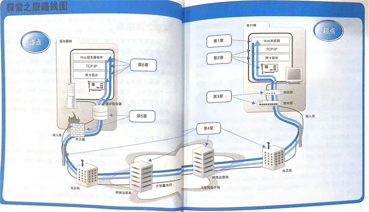
The book is divided into six parts:
- The application layer client generates HTTP and delegates it to the protocol stack of the operating system
- The protocol stack (TCP/IP module) calls the network card driver to generate an electrical signal
- How does the network card reach the router used to access the Internet through the router
- Relay transmission within the Internet
- After arriving at the web server, first pass the firewall check
- How does the web server collect data
The second chapter mainly introduces how the protocol stack and network card in the operating system send application messages to the server:
- Create socket
- Connect server
- Send and receive data
- Disconnect from the server and delete the socket
- Packet sending and receiving operation of IP and Ethernet
- Operation of sending and receiving data with UDP
This paper introduces the fifth chapter, the packet sending and receiving operation of IP and Ethernet.
0. Summary
The IP address is actually assigned to the network card
MAC address is the value written into ROM during network card production
As long as there are receiver MAC address, sender MAC address and Ethernet type, these three features are Ethernet
The main function of ARP protocol is to resolve IP address into physical address
The routing table stores paths to specific network addresses
1. What is a bag
Packet is the transmission data unit of the network layer in the seven layer network model, also known as network packet. Package structure: header + data. The header contains the destination address and other control information. The header can be understood as the face list of express delivery, and the data is the goods in the package
Packet transmission process:
- The sender creates a packet and sends it to the nearest network forwarding device.
- The forwarding device will judge the next forwarding device according to the information in the header. The forwarding process requires a table of addresses
- After multiple forwarding, it reaches the receiving party's network equipment.
The sender and receiver are collectively referred to as terminal nodes, and the forwarding device is an intermediate node.
Create package: generate a header with correct control information (destination address) and attach the data to be sent
What is the table in the network device? Record the sending direction of each address and query in the table according to the destination address in the header.
TCP/IP packet is based on packet, and TCP/IP five layer model is based on network seven layer model.
TCP/IP package encapsulates application layer, transmission layer, network layer and data link layer. The header encapsulates the network layer and data link layer, and the data encapsulates the application layer and transmission layer.
give an example:
Data link layer: Ethernet
Network layer: IP (fixed)
Transport layer: TCP (fixed)
Application layer: HTTP
TCP/IP packet header includes MAC header (for Ethernet protocol) and IP header (for IP Protocol).
The whole process of TCP/IP packet transmission in TCP/IP network:
- The sender writes the destination IP into the IP header. The IP protocol finds the IP of the next router according to this address. The IP protocol finds the Ethernet address according to the IP of the next route and writes it into the MAC header.
- The forwarding device will judge the next forwarding device according to the information in the header. The forwarding process involves routing table and Ethernet table.
- Finally, TCP/IP packets will arrive at the destination.
Reason for division of labor between IP and Ethernet: Ethernet can be replaced by other networks, such as WLAN, FTTH, etc. by separating the network layer and data link layer, various communication technologies can be better used according to needs.
2. Overview of packet sending and receiving operation
How the IP module in the protocol stack completes the sending and receiving operation is the first step of corresponding packet transmission.
Work content of IP module:
- The sender TCP module adds a TCP header in front of the data block and passes it to the IP module. This part is the content of the network packet.
- After receiving the entrustment, the IP module adds the IP header and MAC header (the IP header contains the control information required for sending to the destination, and the MAC header contains the control information for transmitting the packet to the nearest router through the LAN of Ethernet). The IP module sends the TCP/IP packet to the network card, and the network card transfers the binary into photoelectric signal for continuous transmission.
- After receiving the photoelectric signal, the network card of the receiver converts it into a digital signal and transmits it to the IP module. After analyzing the IP header and MAC header, the IP module transmits the data (TCP header + data) to the TCP module.
- The TCP module parses the TCP header and transmits the data to the application.
Key points in sending and receiving:
When sending and receiving data, TCP module will be divided into several stages, and network packets with corresponding functions will be designed for each stage (TCP three handshakes, four waves, etc.).
The sending and receiving operations of IP packets are the same. For the IP module, the TCP header and data are binary data, and the content is not concerned when sending and receiving. In short, the responsibility of IP protocol is to package data and send and receive data.
3. Generate IP header
IP header format
    0                   1                   2                   3
    0 1 2 3 4 5 6 7 8 9 0 1 2 3 4 5 6 7 8 9 0 1 2 3 4 5 6 7 8 9 0 1
   +-+-+-+-+-+-+-+-+-+-+-+-+-+-+-+-+-+-+-+-+-+-+-+-+-+-+-+-+-+-+-+-+
   |Version|  IHL  |Type of Service|          Total Length         |
   +-+-+-+-+-+-+-+-+-+-+-+-+-+-+-+-+-+-+-+-+-+-+-+-+-+-+-+-+-+-+-+-+
   |         Identification        |Flags|      Fragment Offset    |
   +-+-+-+-+-+-+-+-+-+-+-+-+-+-+-+-+-+-+-+-+-+-+-+-+-+-+-+-+-+-+-+-+
   |  Time to Live |    Protocol   |         Header Checksum       |
   +-+-+-+-+-+-+-+-+-+-+-+-+-+-+-+-+-+-+-+-+-+-+-+-+-+-+-+-+-+-+-+-+
   |                       Source Address                          |
   +-+-+-+-+-+-+-+-+-+-+-+-+-+-+-+-+-+-+-+-+-+-+-+-+-+-+-+-+-+-+-+-+
   |                    Destination Address                        |
   +-+-+-+-+-+-+-+-+-+-+-+-+-+-+-+-+-+-+-+-+-+-+-+-+-+-+-+-+-+-+-+-+
   |                    Options                    |    Padding    |
   +-+-+-+-+-+-+-+-+-+-+-+-+-+-+-+-+-+-+-+-+-+-+-+-+-+-+-+-+-+-+-+-+
Three important fields:
Source Address source address, sender IP
Destination Address destination address, receiver IP
Protocol protocol type 6bit: indicates which protocol the packet comes from. TCP protocol number 06 (hexadecimal), UDP number 16 (hexadecimal). For protocol number, see RFC790, ASSIGNED NUMBERS
The IP address is actually assigned to the network card. If a computer has multiple network cards, how can the sender fill in the IP address? How to decide which network card to give the package to?
Judge by routing table.
View the route table instruction route print
IPv4 Routing table
===========================================================================
Active routing:
Network target          Netmask                    gateway          Interface                Metric
        0.0.0.0          0.0.0.0            one hundred and ninety-two.168.0.1     one hundred and ninety-two.168.0.10     50
      one hundred and twenty-seven.0.0.0        255.0.0.0            On link         one hundred and twenty-seven.0.0.1       331
      one hundred and twenty-seven.0.0.1  255.255.255.255            On link         one hundred and twenty-seven.0.0.1    331
 one hundred and twenty-seven.255.255.255  255.255.255.255            On link         127.0.0.1    331
    one hundred and ninety-two.168.0.0    255.255.255.0            On link      one hundred and ninety-two.168.0.10    306
   one hundred and ninety-two.168.0.10  255.255.255.255            On link      192.168.0.10    306
  192.168.0.255  255.255.255.255            On link      192.168.0.10    306
      224.0.0.0        240.0.0.0            On link         127.0.0.1    331
      224.0.0.0        240.0.0.0            On link      192.168.0.10    306
255.255.255.255  255.255.255.255            On link         127.0.0.1    331
255.255.255.255  255.255.255.255            On link      192.168.0.10    306
===========================================================================
Network goal: the ultimate goal of network package
Gateway: IP address of forwarding router. If the gateway is the same as the interface, the packet is sent directly to the target IP.
Interface: sender IP
Metric: transmission cost. The smaller the number, the lower the cost. The metric is - 1 for each forwarding. After the metric changes to 0, the transmission fails.
The network target and netmask are both 0.0.0.0, indicating the default gateway. If the sender IP does not match other network targets, this line is automatically matched.
4. Generate MAC header for Ethernet
The receiver IP indicates the final destination of the packet. If there is no matching network target, the default gateway will be used, and the target MAC address must match the network target.
MAC header
Receiver MAC Address 48 bit
 Sender MAC Address 48 bit
 Ethernet type 16 bit
	0000-05DC: IEEE 802.3
	0800: IP agreement
	0806: ARP agreement
	86DD: IPv6
The MAC address is the value written into the ROM during the production of the network card. To set the sender's MAC, just read and write the MAC address in the network card into the MAC header.
The sender MAC needs to find the IP of the next forwarding device through the routing table, and then query the MAC address according to the IP address.
MAC address: Media Access Control Address, also known as LAN Address, Ethernet Address or Physical Address, which is used to confirm the location of network equipment
5. Query the MAC address of the target router through ARP
ARP: address resolution protocol.
ARP uses Ethernet broadcast to ask all devices: "is this XXX IP yours?", Then someone will answer: "this is mine and my MAC address is XXX".
ARP also has a cache, which can be viewed with the command ARP -a:
  Internet address         Physical address              type
  192.168.0.1           70-af-6a-74-7b-c8     dynamic
  192.168.0.7           24-05-0f-e6-8b-54     dynamic
  192.168.0.255         ff-ff-ff-ff-ff-ff     static state
  224.0.0.2             01-00-5e-00-00-02     static state
  224.0.0.22            01-00-5e-00-00-16     static state
  224.0.0.251           01-00-5e-00-00-fb     static state
  224.0.0.252           01-00-5e-00-00-fc     static state
  239.255.255.250       01-00-5e-7f-ff-fa     static state
  255.255.255.255       ff-ff-ff-ff-ff-ff     static state
The failure time is usually a few minutes. If the corresponding relationship between IP and MAC is changed, it takes a few minutes to take effect.
At this time, the IP module obtains the MAC address, writes it into the MAC header and sends it to the network card. If the data has been packaged before the network card is sent, the network card can adapt to various types of packets.
After TCP header IP header routing table MAC header ARP protocol ARP caching, the IP module is over.
Next, it's the network card's turn.
6. Ethernet Basics
Before introducing the network card, first understand the Ethernet.
At present, Ethernet mostly adopts the switch (switching hub) mode, and the landscape has undergone many changes. As long as there are these three characteristics, it is Ethernet:
- Receiver MAC address
- Sender MAC address
- Ethernet type
Ethernet only cares about the sending and receiving of packets, not the actual content of network packets
7. Convert photoelectric signal into IP packet
IP packet is only a digital signal in memory, which is converted into photoelectric signal by network card.
General structure of network card:
- ROM: the place where the MAC address is stored
- Buffer, temporary storage of network packets
- MAC module, which controls Ethernet transceiver operation
- PHY (MAU), where signals are sent and received
- RJ-45 interface, connecting the base of network cable
The MAC address is unique in the world and is written during production. The MAC address will be read and written into the MAC module from ROM by the network card driver.
8. Add three more control data to the network packet
After the network card driver obtains the package, it will be copied to the buffer of the network card. The MAC module takes out the packet from the network card buffer, adds the header and start frame delimiter at the beginning, and adds FCS (frame check sequence) at the end.
| Header and start frame delimiter | MAC head | IP head | TCP head | ------ data ------| FCS     |
| Network card production          | IP Module production       | TCP production | Application production       | Network card production |