1, Link aggregation overview:
Eth trunk Ethernet link aggregation is called link aggregation for short
The physical link formed by multiple physical ports is bundled into a large logical link to achieve the purpose of [increasing bandwidth]
At the same time, the bundled links [improve link reliability] through mutual dynamic backup
2, Purpose:
The physical link formed by multiple physical ports is bundled into a large logical link to achieve the purpose of [increasing bandwidth]
At the same time, the bundled links [improve link reliability] through mutual dynamic backup
3, Advantages:
1 increase bandwidth
2 improve reliability
3 load sharing (load sharing on the active links of each member can be realized in a link aggregation group)
4, Basic concepts of link aggregation:
1. Link aggregation group and link aggregation interface
Each aggregation group corresponds to a logical interface and can be used as an ordinary Ethernet interface. Different from forwarding, the aggregation group will select one or more of the member interfaces to forward data
2. Member interface and member link
The physical interface constituting the ETH trunk interface is the member interface, and the physical link corresponding to the member interface is the member link
3. Active and inactive interfaces, active and inactive links
The interfaces and links that forward data are active interfaces and links, and the interfaces and links that do not forward data are inactive interfaces and links
4. Maximum number of active interfaces threshold
In order to improve network reliability, when the number of active links reaches the upper limit, add member interfaces to eth trunk, but the number of active interfaces will not be increased. If the number exceeds the threshold, the link will be set to the DOWN state as the standby link
For example, 10 fault free links are an eth trunk, and each 1G bandwidth requires 5G bandwidth at most. Then the upper threshold is set to be greater than or equal to 5, and other links are in standby state
#Note: link aggregation in manual load sharing mode does not support the upper threshold setting of the number of interfaces!!
5. Lower threshold of active interfaces
Set the lower threshold of the number of active interfaces to ensure the minimum bandwidth. When it is less than the set threshold, the state of the ETH trunk interface will change to the Down standby state
For example, the bandwidth of each member link is 1G, and 2G bandwidth is required now, so the lower limit of the number of active interfaces must be greater than or equal to 2
6. Link aggregation mode
The link aggregation mode is divided into manual link aggregation / LACP mode
5, Brief description of two aggregation modes:
According to whether LACP link aggregation control protocol is enabled, it is divided into manual aggregation mode / LACP aggregation mode
Manual mode: (no equipment is required to support LACP protocol, all links in the aggregation group are active links, and one other link shares traffic)
In the manual mode, ETH trunk is established, and the member interfaces are manually configured, without the participation of LACP of link aggregation control protocol
If two direct connected devices are required to provide a large bandwidth and the device does not support LACP protocol, the manual mode can be used
It can increase bandwidth, improve reliability and load sharing
It can detect the open circuit of member links in the same aggregation group
LACP mode: (some active links. After a failure, an inactive link in the automatic reaggregation group is selected as the active link to participate in data forwarding, and the number of active links remains unchanged)
LACP provides a standard negotiation method for data exchange equipment, so that the equipment can automatically form an aggregation link according to its own configuration and start the aggregation link to send and receive data.
After the aggregation link is formed, LACP is responsible for maintaining the link state and automatically adjusting it when the aggregation changes.
Improve the fault tolerance of eth trunk, provide backup function, ensure the reliability of member links, and detect link layer faults and link out of chain faults
It also supports link aggregation across devices
6, LACP mode link aggregation configuration simulation (Cisco simulator)
Simulation description:
Two interactive computers and four PCs, each switch is connected to two PCs, and VLANs are divided to realize cross switch interworking according to the same vlan
The LACP protocol status of the switch port bundle is active, and the switch bundle successfully forms a channel port
Divide VLANs, enter the channel port, call trunk, and ping each other according to the vlan
1. Simulation topology:


2. Command line mode description:
User mode: Switch >
Privileged mode: Switch#
Global configuration mode: Switch(config)#
Port mode: switch (config if) #
3. Aggregation of F0/22-24 ports in SW1 and SW2: (SW1 and 2 have the same configuration)
Switch>enable                  #Enter privileged mode
Switch#config t                #Enter global configuration mode
Switch(config)#hostname SW1    #Renamed SW1 for easy differentiation
SW1(config)#int ra f0/22-24    #f0/22 to 24 ports for aggregation
SW1(config-if-range)#channel-protocol ?           #View support agreement
  lacp  Prepare interface for LACP protocol       #lacp, link aggregation control protocol, IEEE standard
  pagp  Prepare interface for PAgP protocol       #pagp port aggregation protocol is privately owned by Cisco
SW1(config-if-range)#channel-protocol lacp        #Select lacp as the protocol
SW1(config-if-range)#channel-group 1 mode active  #The channel group is 1 and set to active
SW1(config-if-range)#exit  #Exit to global configuration mode
SW1(config)#exit           #Exit to privileged mode again
SW1#show ether su          #You can view the member ports of the current port group and the protocols used
Flags:  D - down        P - in port-channel
        I - stand-alone s - suspended
        H - Hot-standby (LACP only)
        R - Layer3      S - Layer2
        U - in use      f - failed to allocate aggregator
        u - unsuitable for bundling
        w - waiting to be aggregated
        d - default port


Number of channel-groups in use: 1
Number of aggregators:           1

Group  Port-channel  Protocol    Ports
------+-------------+-----------+----------------------------------------------

1      Po1(SU)           LACP   Fa0/22(P) Fa0/23(P) Fa0/24(P)
4. SW2 is also configured according to SW1 configuration, as shown in the figure:

At this time, the links between switches form an aggregate link, which is often regarded as the trunk link between switches
You also need to partition VLANs on the switch and add ports to VLANs
5. Divide VLANs on the switch and add valn to ports (SW1 and 2 are configured the same)
SW1(config)#vlan 10
SW1(config-vlan)#name Vlan1
SW1(config-vlan)#vlan 20
SW1(config-vlan)#name Vlan2
SW1(config-vlan)#int f0/1
SW1(config-if)#sw acc vlan 10
SW1(config-if)#int f0/2
SW1(config-if)#sw acc vlan 20
SW1(config-if)#exit
SW1(config)#exit
SW1#
%SYS-5-CONFIG_I: Configured from console by console

SW1#show vlan

VLAN Name                             Status    Ports
---- -------------------------------- --------- -------------------------------
1    default                          active    Po1, Fa0/3, Fa0/4, Fa0/5
                                                Fa0/6, Fa0/7, Fa0/8, Fa0/9
                                                Fa0/10, Fa0/11, Fa0/12, Fa0/13
                                                Fa0/14, Fa0/15, Fa0/16, Fa0/17
                                                Fa0/18, Fa0/19, Fa0/20, Fa0/21
                                                Fa0/22, Fa0/23, Fa0/24, Gig0/1
                                                Gig0/2
10   Vlan1                            active    Fa0/1
20   Vlan2                            active    Fa0/2
1002 fddi-default                     active
1003 token-ring-default               active
1004 fddinet-default                  active
1005 trnet-default                    active
...
For communication between VLANs, trunk encapsulation shall be performed between switches:
When trunk is encapsulated, port-channel1 port is selected instead of f port, and trunk should be marked under channel group 1
6. trunk packaging
SW1:
SW1>enable
SW1#config t
Enter configuration commands, one per line.  End with CNTL/Z.
SW1(config)#int port-channel 1
SW1(config-if)#sw tr en do
SW1(config-if)#sw mo tr

SW1(config-if)#exit
SW1(config)#exit
SW1#
%SYS-5-CONFIG_I: Configured from console by console

SW1#wr
Building configuration...
[OK]
SW2:
SW2>enable
SW2#config t
Enter configuration commands, one per line.  End with CNTL/Z.
SW2(config)#int port-channel 1
SW2(config-if)#sw tr en do
SW2(config-if)#sw mo tr

SW2(config-if)#exit
SW2(config)#exit
SW2#
%SYS-5-CONFIG_I: Configured from console by console

SW2#wr
Building configuration...
[OK]
7. Mutual ping test
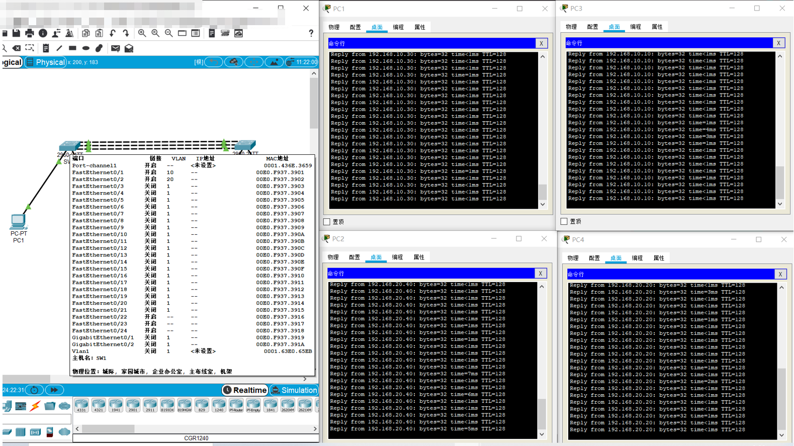
So far, the simulated LACP mode link aggregation has been completed and realized
Two switches and four PCs, each switch is connected to two PCs, and VLANs are divided to realize cross switch interworking according to the same vlan