Spanning tree protocol (STP)
STP overview
Generation of switching network loop
-
Formation of broadcast storm
-
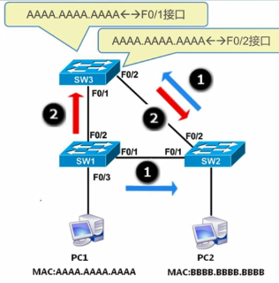
Multiframe copy
-
MAC address table disorder
Introduction to STP
- STP - Spanning Tree Protocol
- Logically disconnect the loop to prevent broadcast storm
- When the line fails, the blocking interface is activated to restore communication and play the role of backup line
Working principle of STP
Spanning tree algorithm and its verification
-
Spanning tree algorithm steps
-
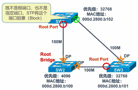
Select the Root Bridge
- The bridge ID is unique
- The switch with the smallest bridge ID in the switching network is called the root bridge
- Bridge composition: Bridge priority (2 bytes) + MAC address of the bridge (6 bytes)
- Value range: 0 ~ 65535 default value: 32768
-
Select Root Ports (on non root bridges, select a root port)
-
Lowest root path cost to root bridge
The sum of the costs of all links on the root path from the bridge to the root bridge
Relationship between bandwidth and path cost
Link bandwidth (Mbps) Path cost 10 100 16 62 45 39 100 19 155 14 622 6 1000 4 10000 2 -
Minimum direct bridge ID
-
Minimum port ID (compare the port on the root bridge and the port opposite the minimum ID)
- Port ID: port priority (2 digits) + port number (8 digits)
- Value range: 0 ~ 255
- Default value: 128
-
-
Select Designated Ports
-
The ports on the root bridge are all specified ports
-
On each network segment, select a specified port
-
Specified port on non root bridge, select order
Lower root path cost
The value of the bridge ID of the switch is small
The value of the port ID is small
-
-
Finally, a logical structure acyclic topology is formed
-
BPDU (bridge protocol data unit)
-
BPDU
Bridge Protocol Data Unit
Sending BPDU using multicast
-
BPDU type
Configuration BPDU
Topology change notification (TCN) BPDU
-
BPDU message field
Root bridge ID, root path cost, send bridge ID, port ID
-
STP uses BPDU to select the root bridge
- When the switch starts, it is assumed that it is the root bridge, and then fill in its own bridge ID in the root bridge ID field of the BPDU sent out
- After receiving the BPDU sent by other switches, compare the bridge ID and select the smaller one to add to the root bridge ID
Convergence of STP
-
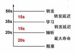
STP status of switch port
state purpose Forwarding Send / receive user data Learning Build bridge table Listening Building an activity topology Blocking Receive BPDU only Disabled Force close -
STP timer
-
Hello Time
-
Forwarding delay
-
Maximum aging time
-
Application of STP
Relationship between STP and VLAN
- IEEE common spanning tree (CST) does not consider VLAN, and one VLAN link may be disconnected
- PVST (Cisco private, Huawei MSTP) constructs a spanning tree instance for each VLAN to realize network load sharing (balancing)
- The mapping relationship between spanning tree instances and VLANs. The data of the same VLAN can only correspond to one instance, and one instance can correspond to multiple VLANs
MSTP configuration command
Configuration case of MSTP
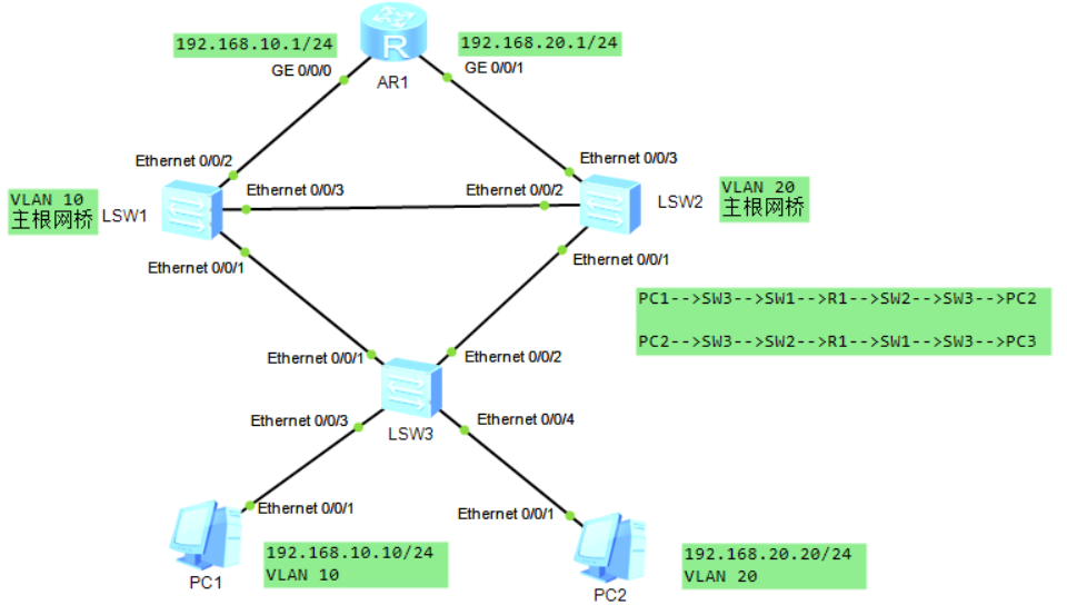
Router R1 configuration
[r1]int g0/0/0
[r1-GigabitEthernet0/0/0]ip add 192.168.10.1 24
[r1-GigabitEthernet0/0/0]q
[r1]int g0/0/1
[r1-GigabitEthernet0/0/1]ip add 192.168.20.1 24
Switch SW1 configuration
[sw1]vlan batch 10 20
Info: This operation may take a few seconds. Please wait for a moment...done.
[sw1]in e0/0/1
[sw1-Ethernet0/0/1]port link-type trunk
[sw1-Ethernet0/0/1]port trunk allow-pass vlan all
[sw1-Ethernet0/0/1]in e0/0/3
[sw1-Ethernet0/0/3]port link-type trunk
[sw1-Ethernet0/0/3]port trunk allow-pass vlan all
[sw1-Ethernet0/0/3]in e0/0/2
[sw1-Ethernet0/0/2]port link-type access
[sw1-Ethernet0/0/2]port default vlan 10
[sw1-Ethernet0/0/2]quit
[sw1]stp mode mstp                          ### Configure the switch to MSTP mode, which is compatible with STP/RSTP
[sw1]stp region-configuration               ### Enter MSTP domain view MSTP configuration mode
[sw1-mst-region]region-name nrh ##Configure the domain name of MSTP domain, which defaults to the MAC address of the management network interface on the main control board of the switching device
[sw1-mst-region]revision-level 1
     ### The revision level is 1. By default, the MSTP revision level of the MSTP domain is 0. It is necessary to modify the MSTP revision level of each device to be consistent
[sw1-mst-region]instance 10 vlan 10         ### Add vlan 10 to instance 10
[sw1-mst-region]instance 20 vlan 20         ### Add vlan 20 to instance 20
[sw1-mst-region]check region-configuration  ### View MSTP domain configuration parameters
 Admin configuration
   Format selector    :0
   Region name        :nrh
   Revision level     :1

   Instance   VLANs Mapped
      0       1 to 9, 11 to 19, 21 to 4094
     10       10
     20       20
[sw1-mst-region]active region-configuration ### Activate the configuration of MSTP domain (required)
Info: This operation may take a few seconds. Please wait for a moment...done.
[sw1-mst-region]q                           ### Exit configuration mode
[sw1]stp instance 10 root primary           ### Configure this switch as the primary root bridge of instance 10
[sw1]stp instance 20 root secondary         ### Configure this switch as the backup bridge of instance 20
[sw1]stp enable
[sw1]dis stp brief
 MSTID  Port                        Role  STP State     Protection
   0    Ethernet0/0/1               DESI  FORWARDING      NONE
   0    Ethernet0/0/2               DESI  FORWARDING      NONE
   0    Ethernet0/0/3               DESI  FORWARDING      NONE
  10    Ethernet0/0/1               DESI  FORWARDING      NONE
  10    Ethernet0/0/2               DESI  FORWARDING      NONE
  10    Ethernet0/0/3               DESI  FORWARDING      NONE
  20    Ethernet0/0/1               DESI  FORWARDING      NONE
  20    Ethernet0/0/3               ROOT  FORWARDING      NONE
Configuration of switch SW2
[sw2]vlan batch 10 20
Info: This operation may take a few seconds. Please wait for a moment...done.
[sw2]int e0/0/1
[sw2-Ethernet0/0/1]port link-type trunk
[sw2-Ethernet0/0/1]port trunk allow-pass vlan all
[sw2-Ethernet0/0/1]int e0/0/3
[sw2-Ethernet0/0/3]quit
[sw2]int e0/0/2
[sw2-Ethernet0/0/2]port link-type trunk
[sw2-Ethernet0/0/2]port trunk allow-pass vlan all
[sw2-Ethernet0/0/2]int e0/0/3
[sw2-Ethernet0/0/3]port link-type access
[sw2-Ethernet0/0/3]port default vlan 20
[sw2-Ethernet0/0/3]quit
[sw2]stp mode mstp
[sw2]stp region-configuration
[sw2-mst-region]region-name nrh
[sw2-mst-region]revision-level 1
[sw2-mst-region]instance 10 vlan 10
[sw2-mst-region]instance 20 vlan 20
[sw2-mst-region]active region-configuration
Info: This operation may take a few seconds. Please wait for a moment...done.
[sw2-mst-region]quit
[sw2]stp instance 10 root secondary        ### Configure SW1 switch as the backup bridge of instance 1
[sw2]stp instance 20 root primary          ### Configure SW2 switch as the primary root bridge of instance 2
[sw2]stp enable                            ### Start MSTP
[sw2]dis stp brief
 MSTID  Port                        Role  STP State     Protection
   0    Ethernet0/0/1               DESI  FORWARDING      NONE
   0    Ethernet0/0/2               ROOT  FORWARDING      NONE
   0    Ethernet0/0/3               DESI  FORWARDING      NONE
  10    Ethernet0/0/1               DESI  FORWARDING      NONE
  10    Ethernet0/0/2               ROOT  FORWARDING      NONE
  20    Ethernet0/0/1               DESI  FORWARDING      NONE
  20    Ethernet0/0/2               DESI  FORWARDING      NONE
  20    Ethernet0/0/3               DESI  FORWARDING      NONE
Configuration of switch SW3
[sw3]vlan batch 10 20
Info: This operation may take a few seconds. Please wait for a moment...done.
[sw3]int e0/0/3
[sw3-Ethernet0/0/3]p l a
[sw3-Ethernet0/0/3]p d v 10
[sw3-Ethernet0/0/3]int e0/0/4
[sw3-Ethernet0/0/4]p l a
[sw3-Ethernet0/0/4]p d v 20
[sw3-Ethernet0/0/4]int e0/0/1
[sw3-Ethernet0/0/1]p l t
[sw3-Ethernet0/0/1]p t a v a
[sw3-Ethernet0/0/1]int e0/0/2
[sw3-Ethernet0/0/2]p l t
[sw3-Ethernet0/0/2]p t a v a
[sw3-Ethernet0/0/2]quit
[sw3]stp mode mstp
[sw3]stp region-configuration
[sw3-mst-region]region-name nrh
[sw3-mst-region]revision-level 1
[sw3-mst-region]instance 10 vlan 10
[sw3-mst-region]instance 20 vlan 20
[sw3-mst-region]active region-configuration
Info: This operation may take a few seconds. Please wait for a moment...done.
[sw3-mst-region]q
[sw3]stp enable
[sw3]dis stp brief
 MSTID  Port                        Role  STP State     Protection
   0    Ethernet0/0/1               ROOT  FORWARDING      NONE
   0    Ethernet0/0/2               ALTE  DISCARDING      NONE
   0    Ethernet0/0/3               DESI  FORWARDING      NONE
   0    Ethernet0/0/4               DESI  FORWARDING      NONE
  10    Ethernet0/0/1               ROOT  FORWARDING      NONE
  10    Ethernet0/0/2               ALTE  DISCARDING      NONE
  10    Ethernet0/0/3               DESI  FORWARDING      NONE
  20    Ethernet0/0/1               ALTE  DISCARDING      NONE
  20    Ethernet0/0/2               ROOT  FORWARDING      NONE
  20    Ethernet0/0/4               DESI  FORWARDING      NONE
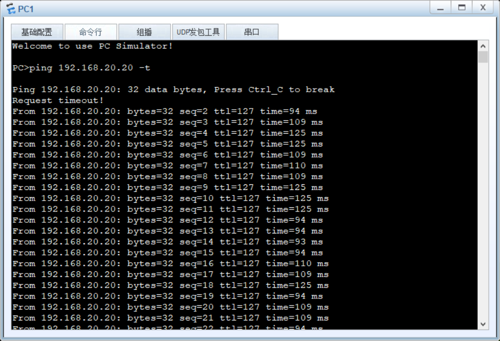
Verify connectivity