This article takes you to understand the working principle and code writing of LCD1602 LCD in detail
LCD1602 LCD
LCD (short for Liquid Crystal Display) Liquid Crystal Display. It can display 16x2 and 32 characters at the same time. It is a dot matrix LCD module specially used to display letters, numbers, symbols, etc.
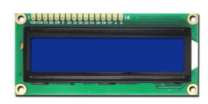
LCD1602 LCD is a widely used character LCD module. It is composed of character liquid crystal display (LCD), control and drive main circuit HD44780 and its extended drive circuit HD44100, as well as a small number of resistance, capacitor elements and structural parts assembled on the PCB. The display screen has the advantages of low power consumption, small volume and low radiation.
LCD1602 is mainly used to display numbers, letters, graphics and a small number of custom characters. It can display two lines of 16 characters and has 16 pins, including 8-bit data bus D0-D7, and three control ports of RS, R/W and EN. The working voltage is 5V, and it is equipped with character contrast adjustment V0 and backlight AK.
Note:
The LCD screen we use is basically named according to its resolution. For example, the resolution of LCD 1602 is 16 × 2 LCD 12864 has a resolution of 128 × sixty-four
LCD1602 main parameters
- Display character: 16 × 2 characters
- Working voltage: 4.5~5V
- Working current: 2.0mA
- Operating temperature: - 20 ° C~70 ° C
- Optimum working voltage of module: 5.0V
- Single character size 2.95 × 4.35(W × Hmm)
- Pin: 16 pin
LCD luminous principle
First of all, you should know:
-
Liquid crystal: liquid crystal is a liquid crystal. It is an almost transparent substance and cannot emit light
-
Light source: the light of LCD screen comes from the light source emitted by the backlight panel at the bottom of the screen
-
Polarizer: a lens through which only light in a specific direction (vertically polarized light) can pass, while light in other directions cannot pass
-
The fence angles of the two polarizers are perpendicular to each other, and the light line cannot pass through at all
The physical characteristics of liquid crystal are: the degree of light passing through the liquid crystal is controlled by the voltage applied to the liquid crystal. When the power is on, the arrangement becomes orderly, making it easy for light to pass through and the path of light does not change; When there is no electricity, the arrangement is chaotic, preventing the light from passing through and changing the path of light.
Composition of LCD screen:
The upper polarizer and the lower polarizer make the light of the backlight only pass through the lower polarizer, not through the lower polarizer
Color filter: light with different intensities will form various colors after passing through the red, green and blue filter
Liquid crystal layer: the molecular arrangement of liquid crystal is controlled by power on, so as to change the path of light emitted by the backlight. If power on, the path will not be changed, and the light cannot pass through the upper polarizer. If power off, the path of light will be changed, and the light can pass through the upper polarizer for display.
TFT substrate: thin film transistors arranged in order. Each thin film transistor can adjust its voltage, so that the liquid crystal within the range of a single transistor can display different brightness and color, that is, the pixel
Backlight: provides a uniform background light
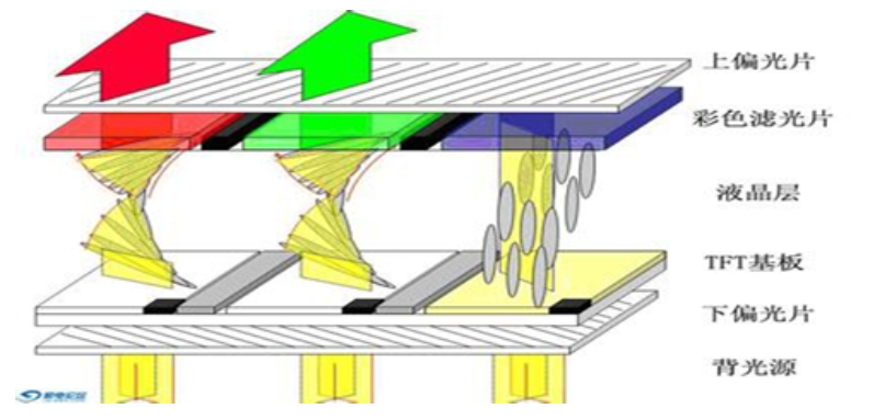
In other words, if you want the LCD screen not to display, you only need the light of the backlight not to pass through the upper polarizer. If you need the LCD screen to display characters, you need the light of the backlight to pass through the upper polarizer. Whether it can pass through the upper polarizer depends on the molecular arrangement of the liquid crystal layer, which is controlled by the voltage applied to the liquid crystal,
That is, finally, we only need to control the voltage of each pixel to achieve the effect of LCD screen display. In this way, the liquid crystals can be rearranged through the voltage control of different areas to display various graphics, images and characters.
Differences between LCD and OLED:
LCD (short for Liquid Crystal Display) Liquid Crystal Display.
OLED (organic light emitting diode) is essentially an LED light-emitting diode. When a forward voltage is applied at both ends, the carriers in the semiconductor recombine and cause photon emission to produce light, which is also called electromechanical laser display.
In short, LCD and LED are two different display technologies. LCD is a display screen composed of liquid crystals, while LED is a display screen composed of light-emitting diodes. The second essential difference is that LCD needs backlight to light up. OLED is self luminous LED and does not need additional light source
LCD1602 pin wiring:
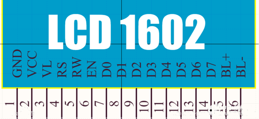
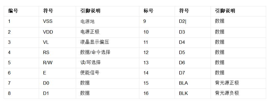
The functions of each pin are described as follows:
-
Pin 1(VSS/GND): ground pin
-
Pin 2(VDD/VCC): power pin
-
Pin 3(VL): LCD contrast pin. The contrast is the weakest when connected to the positive power supply and the highest when connected to the ground. When in use, its contrast can be adjusted through an external potentiometer.
-
Pin 4(RS): register selection pin, select data register at high level and instruction register at low level.
-
Pin 5(R/W): read / write signal line. Read at high level and write at low level. When RS and R/W are at low level together, the instruction or display address can be written; When RS is low level and R/W is high level, the busy signal can be read; When RS is high level and R/W is low level, data can be written.
-
Pin 6(E): enable end. When e end jumps from high level to low level, the LCD module executes the command.
-
Pin 7-14(D0~D7): 8-bit bidirectional data line is used for MCU to write data to and read data from 1602
-
Pin 15: backlight cathode
-
Pin 16: backlight negative pole
LCD1602 has 16 pins in total, but the classification is very good,
One of the VCC and GND is used to supply power to 1602,
A VCC and GND are used to supply power to the backlight,
There are three functional pins left: RS (data command selection end), R/W (read / write selection end), E (enable signal),
There are also eight D0~D7, which are 8-bit bidirectional data lines to transmit data.
- RS is register selection, high level selects data register and low level selects instruction register.
- R/W is the read / write selection. Read operation is performed at high level and write operation is performed at low level.
- E end is the enabling end, which is later associated with timing.
RAM address mapping and standard font table of LCD1602
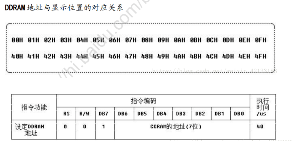
LCD1602 is displayed in 16 rows and 2 columns in total, corresponding to 32 RAM addresses. When using, write the corresponding RAM address in which position it needs to be displayed, and then write the required character, and the corresponding character will be displayed.
The LCD module is a slow display device, so before executing each instruction, be sure to confirm that the busy flag of the module is low level, indicating that the LCD is not busy at this time. At this time, you can write instructions and data, otherwise this instruction will be invalid. To display characters, first input the display character address (write instruction), that is, tell the module where to display characters, and then write the characters to be displayed (write data), so as to display characters normally
The following figure shows the internal display address of 1602
There are 32 addresses in total, corresponding to 2 rows and 16 columns
Standard font table (CGROM):
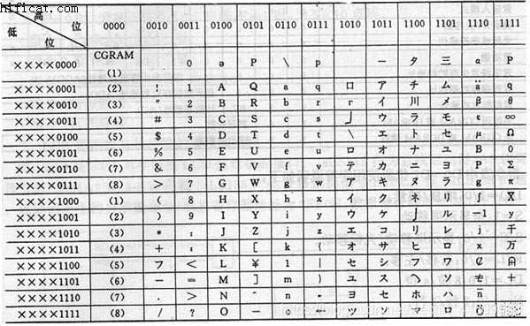
This ROM solidifies the dot matrix data of some commonly used ASCII characters and some Japanese characters. If you need to write that character, you can directly set the corresponding hexadecimal code. For example, the uppercase letter A, the code is 0100 0001 (41H), which is consistent with the ASCII code. That is, the address of ASCII characters in the table is the same as the actual ASCII characters
LCD1602 read / write operation
LCD1602 is divided into read operation and write operation
The read operation can be divided into read state and read data, and the write operation can be divided into write instruction and write data.
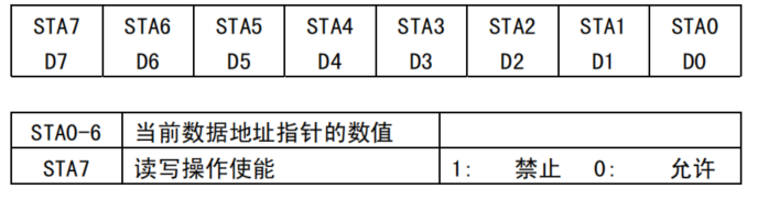
Read status: read the LCD pin status and return to the status word. D0-D6 is the address of the current LCD data pointer. D7 is whether reading and writing operation is allowed (i.e. check whether the LCD is in the busy state)
Read data: read data in D0-07
Write command: write the control command of LCD, such as screen clearing, display switch, etc
Write data: write the data to be displayed. For example, to display character a, write 0100 0001 (41H)
| Read state | |
|---|---|
| Pin level: RS=L,RW=H,E=H | Output: D0~D7 = status word |
| Read data | |
|---|---|
| Pin level: RS=H,RW=H,E=H | Output: data of D0~D7 |
| Write instruction | |
|---|---|
| Pin level: RS=L,RW=L,D0~D7 = instruction code, E = high pulse | Output: None |
| Write data | |
|---|---|
| Pin level: RS=H,RW=L,D0~D7 = data, E = high pulse | Output: None |
Taking 51 single chip microcomputer as an example, D0-D7 is connected to port P0 and RW en is connected to any two ports
The sequence diagram of read-write operation is as follows:
Read operation sequence:
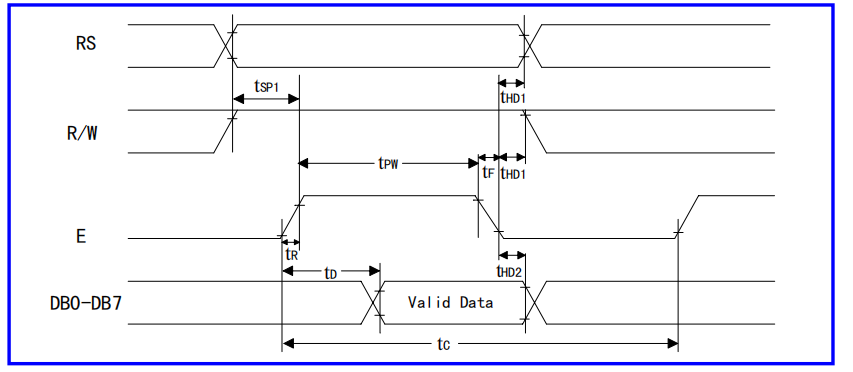
Write sequence:
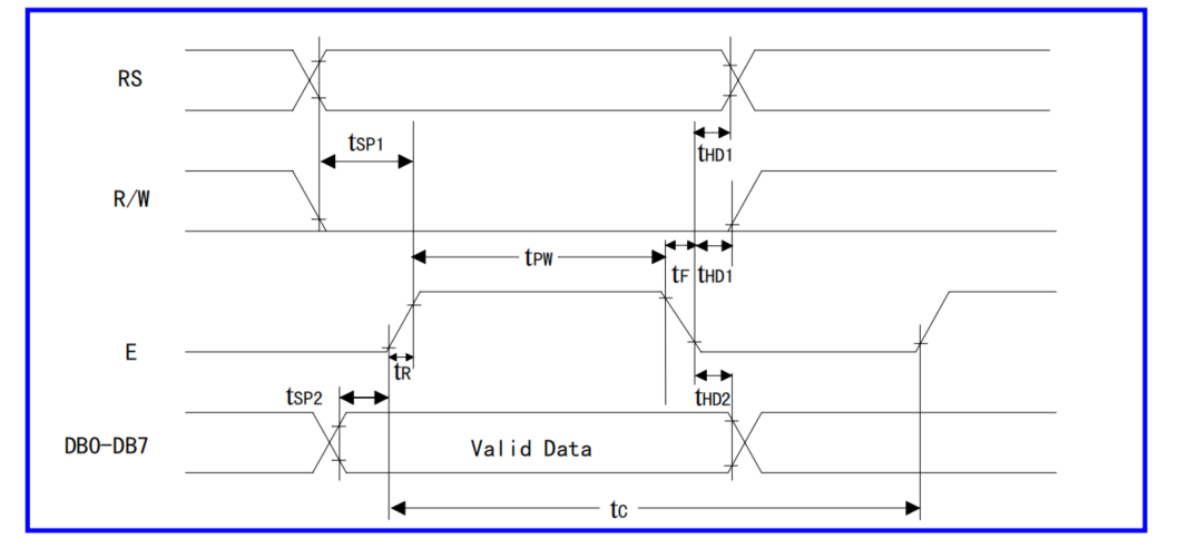 Let's analyze the timing chart. When we want to write an instruction, RS is set to low level, RW is set to low level, en is set to low level, and then the instruction data is sent to data ports D0~D7, delaying tsp1 to make 1602 ready to receive data. At this time, EN is pulled up to produce a rising edge. At this time, the instruction starts to write to LCD, delaying for a period of time, and en is set to low level.
When we want to write data, RS is set to low level, RW is set to high level, EN is set to low level, and then the instruction data is sent to data ports D0~D7, delaying tsp1, so that 1602 is ready to receive data. At this time, EN is pulled up to generate a rising edge. At this time, the data starts to be written to LCD, delaying for a period of time, and EN is set to low level.
Let's take 51 single chip microcomputer as an example. D0-D7 is connected to port P0. If there are any three pins of RW and RW en, the write instruction and write data codes are as follows:
Write instruction:
/*********************************************************/
// 1602 LCD write command function, cmd is the command to write
/*********************************************************/
void LcdWriteCmd(uchar cmd)
{
	LcdRs_P = 0;  //Select write instruction
	LcdRw_P = 0; 	//Select write
	LcdEn_P = 0;  //E enable pull down
	P0=cmd;  //Send instruction to P0
	DelayMs(2); //After a short delay, 1602 is ready to receive data
	LcdEn_P = 1;  //The rising edge of the level change of the enable line sends the command to the 8-bit data port of 1602
	DelayMs(2);//Delay to send data
	LcdEn_P = 0;	//Enable line pulled low
}
Write data:
/*********************************************************/
// 1602 LCD write data function, dat is the data to be written
/*********************************************************/
void LcdWriteData(uchar dat)
{
	LcdRs_P = 1;  //Select write data
	LcdRw_P = 0; //Select write
	LcdEn_P = 0; //E enable pull down
	P0=dat;   //Send data to P0
	DelayMs(2); //After a short delay, 1602 is ready to receive data
	LcdEn_P = 1;  //The rising edge of the level change of the enable line sends the command to the 8-bit data port of 1602
	DelayMs(2);//Delay to send data
	LcdEn_P = 0;//Enable line pulled low
}
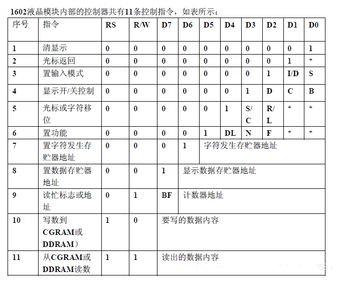
Instruction operation of LCD1602
There are 11 instructions in LCD1602. Let's interpret them one by one,
The reading and writing operation of 1602 LCD module and the operation of screen and cursor are realized through instructions. (1 is high level and 0 is low level)
Instruction 1: clear display, instruction code 01H,
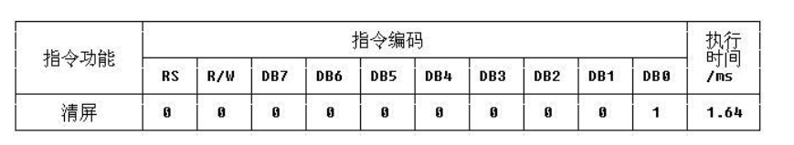 Function:
- Reset the cursor to address 00H,
- LCD displays that the contents of DDRAM are all written into "ASCII code 20H
Instruction 2: reset the cursor and return the cursor to address 00H
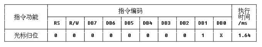
Function:
- Reset the cursor to address 00H
- The LCD displays the contents of DDRAM unchanged
Instruction 3: cursor and display position setting
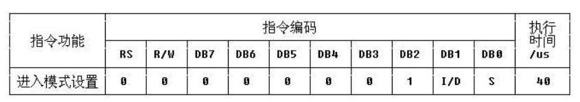
Function:
- I/D, cursor moving direction after writing new data, high level moving right, low level moving left,
- S: After writing new data, whether the characters on the display screen are shifted left or right by one character as a whole. High level indicates valid and low level indicates invalid
Command 4: display switch control
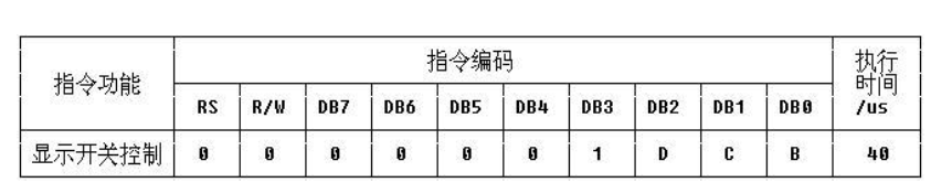 Function:
- D (dispense): control the overall display on and off. High level means to turn on the display screen and low level means to turn off the display screen
- C(Cursor): controls the opening and closing of the cursor. High level indicates that there is a cursor and low level indicates that there is no cursor
- B(Blink): control whether the cursor flickers, high level flickers and low level does not flicker
Instruction 5: cursor or display shift
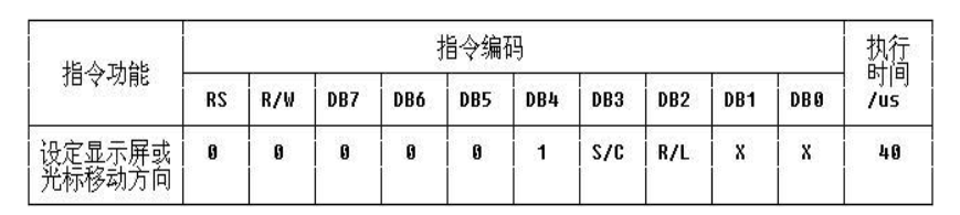
- SC=0, RL=0: cursor moves left
- SC=0, RL=1: cursor moves to the right
- When SC=1 and RL=0, the character and cursor move to the left
- When SC=1 and RL=1, the character and cursor move to the right
Instruction 6: function setting command
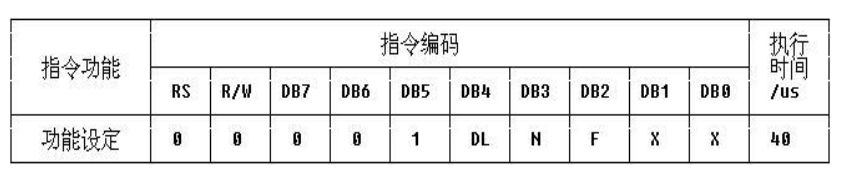
- DL: DL=1 means the data length is 8 bits, DL=0 means the data length is 4 bits
- N: Only one line can be displayed at low level, and both lines can be displayed at high level,
- F: A dot matrix character with a character size of 5X7 at low level and a dot matrix character with a character size of 5X10 at high level.
Instruction 7: CGRAM address setting

Function:
- The CGRAM of LCD1602 can be set to store custom characters. It has 6 bits and can represent 64 addresses, i.e. 64 bytes. One 5 × 8 dot matrix characters occupy 8 bytes in total, so the 64 bytes can customize 8 characters in total.
Instruction 8: DDRAM address setting
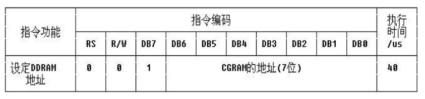
- Specify DDRAM address
Instruction 9: read busy signal and cursor address
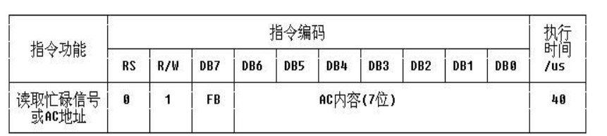
- BF: busy flag bit. High level indicates busy. At this time, the module cannot receive commands or data. If low level indicates not busy
Instruction 10: write data to CGRAM or DDRAM instruction
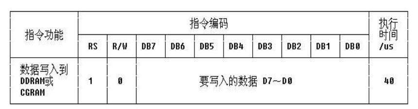
- Instruction 11 ·: read data instruction from CGRAM or DDRAM

Function: - Read the contents of DDRAM or CGRAM
LCD initialization
The process of LCD initialization is the process of writing instructions to LCD. The specific instructions are as follows:
- Write instruction 38H: 162 display, 57 dot matrix, 8-bit data port (instruction 6)
- Write command 0CH: turn on the display screen, turn off the cursor, and the cursor does not flash (command 4)
- Write instruction 0x06: add 1 to the display address, that is, after writing a data, the display position shifts one bit to the right (instruction 3)
- Write instruction 01H: display clear screen
/*********************************************************/
// 1602 LCD function initialization
/*********************************************************/
void LcdInit()
{
	LcdWriteCmd(0x38);        // 16 * 2 display, 5 * 7 dot matrix, 8-bit data port
	LcdWriteCmd(0x0C);        // On display, no cursor
	LcdWriteCmd(0x06);        // Add 1 to the address and move the cursor to the right after writing data
	LcdWriteCmd(0x01);        // Clear screen
}
LCD write address
In fact, the essence is instruction 8, but when we write, the highest bit D7 is required to be 1, that is, it is actually a 7-bit address
For example, if we want to write the first column in the second row, the address is 40H(0100 0000). Is it OK to write it directly?, Obviously not, because the highest D7 is not 1 Therefore, you need to add an 80H(1000 0000), that is, the actually written value is 40H(0100 0000)+80H(1000 0000)=C0H(1100 0000)
In this case, the starting address of the first line is (10 million) 80h, and the starting address of the second line is (11 million) C0H
The code is as follows:
/*********************************************************/
// LCD cursor positioning function
/*********************************************************/
void LcdGotoXY(uchar line,uchar column)
{
	// first line
	if(line==0)
		LcdWriteCmd(0x80+column);
	// Second line
	if(line==1)
		LcdWriteCmd(0x80+0x40+column);
}
LCD write data
This is relatively simple. You can directly use a pointer to judge whether the character ends, and then write data
/*********************************************************/
// LCD output string function
/*********************************************************/
void LcdPrintStr(uchar *str)
{
	while(*str!='\0')
			LcdWriteData(*str++);
}
Code and application examples:
Here we use Proteus simulation for demonstration
Function: LCD1602 English display characters
The code is as follows:
#include <reg52.h>
#include <intrins.h>

#define uchar unsigned char 	//  In the future, unsigned char can be replaced by uchar
#define uint  unsigned int 	//  In the future, unsigned int can be replaced by uint

sbit LcdRs_P   = P1^1;			// RS pin of 1602 LCD
sbit LcdRw_P   = P1^2;			// RW pin of 1602 LCD
sbit LcdEn_P   = P1^3;			// EN pin of 1602 LCD


/*********************************************************/
// Millisecond delay function. time is the number of milliseconds to delay
/*********************************************************/
void DelayMs(uint time)
{
	uint i,j;
	for(i=0;i<time;i++)
		for(j=0;j<112;j++);
}


/*********************************************************/
// 1602 LCD write command function, cmd is the command to write
/*********************************************************/
void LcdWriteCmd(uchar cmd)
{
	LcdRs_P = 0;
	LcdRw_P = 0;
	LcdEn_P = 0;
	P0=cmd;
	DelayMs(2);
	LcdEn_P = 1;
	DelayMs(2);
	LcdEn_P = 0;
}


/*********************************************************/
// 1602 LCD write data function, dat is the data to be written
/*********************************************************/
void LcdWriteData(uchar dat)
{
	LcdRs_P = 1;
	LcdRw_P = 0;
	LcdEn_P = 0;
	P0=dat;
	DelayMs(2);
	LcdEn_P = 1;
	DelayMs(2);
	LcdEn_P = 0;
}


/*********************************************************/
// LCD cursor positioning function
/*********************************************************/
void LcdGotoXY(uchar line,uchar column)
{
	// first line
	if(line==0)
		LcdWriteCmd(0x80+column);
	// Second line
	if(line==1)
		LcdWriteCmd(0x80+0x40+column);
}


/*********************************************************/
// LCD output string function
/*********************************************************/
void LcdPrintStr(uchar *str)
{
	while(*str!='\0')
			LcdWriteData(*str++);
}


/*********************************************************/
// 1602 LCD function initialization
/*********************************************************/
void LcdInit()
{
	LcdWriteCmd(0x38);        // 16 * 2 display, 5 * 7 dot matrix, 8-bit data port
	LcdWriteCmd(0x0C);        // On display, no cursor
	LcdWriteCmd(0x06);        // Add 1 to the address and move the cursor to the right after writing data
	LcdWriteCmd(0x01);        // Clear screen
}

/*********************************************************/
// Turn on LCD1602 display
/*********************************************************/
void LcdOn()   //Turn on the display, turn off the cursor and flash
{
	LcdWriteCmd(0x0c);
}
/*********************************************************/
//Turn off the LCD1602 display, but the content in DDRAM will not be lost. After reopening, the content will be restored

/*********************************************************/
void LcdOff()
{
	LcdWriteCmd(0x08);
}

/*********************************************************/
// 1602 LCD content initialization
/*********************************************************/
void LcdShowInit()
{
	LcdGotoXY(0,0);	    							// Navigate to row 0, column 0
	LcdPrintStr("   LCD Test  ");	// Line 0 shows ""
	LcdGotoXY(1,0);	    							// Navigate to row 1, column 0
	LcdPrintStr("ABCDEFGHIJKLMNOP");	// Line 1 shows ""
}


/*********************************************************/
// Main function
/*********************************************************/
void main()
{
	LcdInit();								// LCD function initialization
	LcdShowInit();

	while(1)
	{
	}
}
The test results are as follows: