1 reason
Learning coordinate transformation requires strong spatial imagination. It is best to have a certain perceptual understanding in combination with actual cases, otherwise it is difficult to imagine out of thin air after several rotations of the coordinate axis. Therefore, the author uses Matlab AppDesigner to demonstrate the aircraft coordinate transformation GUI. Through interface interaction and three-dimensional animation demonstration, it can help users establish their perceptual knowledge of coordinate transformation.
2 Schematic
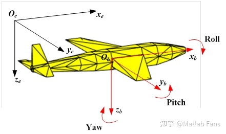
Ground coordinate system : fixed with the ground, regarded as a fixed coordinate system;
Body coordinate system  : the coordinate system fixed with the aircraft body and moving with the aircraft;
Roll angle: around  Axis rotation angle (from
  Axis (counterclockwise is positive);
Pitch angle: around  Axis rotation angle (from
  Axis (counterclockwise is positive);
Yaw angle:  Axis rotation angle (from
  Axis (counterclockwise is positive);
It is assumed that the ground coordinate system coincides with the body coordinate system in the initial state (when the roll angle, pitch angle and yaw angle are all 0). After the aircraft roll, pitch or yaw action, there is an included angle between the body coordinate system and the ground coordinate system. According to the rotating Euler angle (roll angle, pitch angle and yaw angle), the coordinate transformation matrix from the body coordinate system to the ground coordinate system can be obtained, so that the physical quantities in the body coordinate system can be transformed into the ground coordinate system for description, On the contrary, the physical quantities in the ground coordinate system can also be converted to the body coordinate system for description.
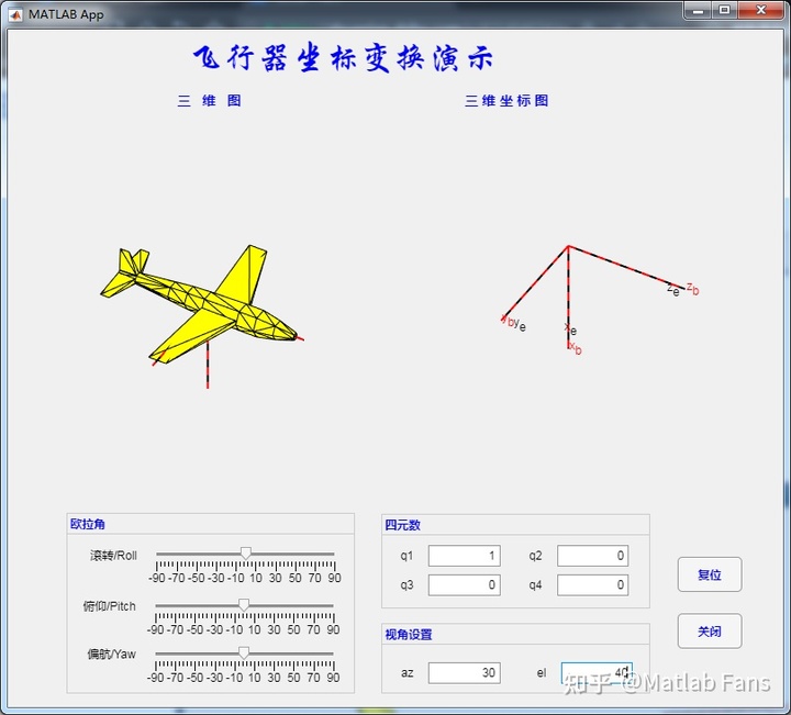
3 interface
4 demonstration
4.1 rolling action

4.2 pitching action

4.3 yaw action
5 some methods
5.1 aircraft 3D model drawing method
The aircraft is approximately drawn using several triangular surface meshes. Firstly, the position coordinates of each node of the triangular mesh are obtained, and then the connection relationship of each node of the triangular mesh is defined. Then, the fill surface graph is drawn using the patch function, and the triangular surfaces are connected in turn according to the node definition to form the outline of the aircraft. The drawing procedure of aircraft 3D model is as follows:
% X For node coordinate data
X =  [[0.4 0.025 -0.0433012701892219;0.4 0.05 0;0.4 0.025 0.0433012701892219;0.4 -0.025 0.0433012701892219;0.3 -0.035 0.0606217782649107;0.2 0.035 0.0606217782649107;0.2 0.07 0;0 0.065 0;-0.1 0.03 0.0519615242270663;-0.1 -0.03 0.0519615242270663;-0.2 -0.025 0.0433012701892219;-0.3 -0.04 0;-0.2 -0.05 0;-0.1 -0.06 0;0 -0.065 0;0 -0.0325 0.0562916512459885;0 -0.0325 -0.0562916512459885;-0.1 0.03 -0.0519615242270663;-0.1 0.06 0;-0.1 -0.03 -0.0519615242270663;-0.4 0.015 -0.0259807621135332;-0.4 0.03 0;-0.5 0.02 0;-0.2 -0.025 -0.0433012701892219;-0.4 -0.03 0;-0.4 -0.015 0.0259807621135332;-0.5 -0.01 0.0173205080756888;-0.2 0.025 0.0433012701892219;-0.4 0.015 0.0259807621135332;-0.5 0.01 0.0173205080756888;-0.5 -0.01 -0.0173205080756888;-0.5 -0.02 0;-0.4 -0.015 -0.0259807621135332;-0.3 0.04 0;-0.2 0.025 -0.0433012701892219;0 0.0325 -0.0562916512459885;0.2 -0.035 -0.0606217782649107;0.2 0.035 -0.0606217782649107;0.3 0.035 -0.0606217782649107;0.3 0.07 0;0.5 -0.01 -0.0173205080756888;0.5 -0.02 0;0.5 -0.01 0.0173205080756888;0.4 -0.05 0;0.4 -0.025 -0.0433012701892219;0.3 -0.035 -0.0606217782649107;0.3 -0.07 0;0.2 -0.07 0;0.2 -0.035 0.0606217782649107;0.5 0.01 -0.0173205080756888;0.5 0.02 0;0.3 0.035 0.0606217782649107;0.5 0.01 0.0173205080756888;0 0.0325 0.0562916512459885;-0.2 0.05 0;-0.5 0.01 -0.0173205080756888;0.2 0.0657784834550136 0.0239414100327968;0 0.0562916512459885 -0.0325;0.05 0.5 0;0.2 0.07 -0;0 0.061080020351084 0.0222313093161685;-0.05 0.5 0;0 -0.0562916512459885 -0.0325;0.2 -0.0657784834550136 0.0239414100327968;0.05 -0.5 0;0.2 -0.07 -0;-0.05 -0.5 0;0 -0.061080020351084 0.0222313093161685;-0.45 0.2 0;-0.4 0.0259807621135332 0.015;-0.4 0.0259807621135332 -0.015;-0.5 0.0173205080756888 -0.01;-0.5 0.2 0;-0.5 0.0173205080756888 0.01;-0.4 -0.0259807621135332 0.015;-0.4 -0.0259807621135332 -0.015;-0.45 -0.2 0;-0.5 -0.0173205080756888 -0.01;-0.5 -0.0173205080756888 0.01;-0.5 -0.2 0;-0.4 0.012678547852221 0.0271892336110995;-0.4 -0.012678547852221 0.0271892336110995;-0.45 0 0.15;-0.5 -0.00845236523481399 0.018126155740733;-0.5 0.00845236523481399 0.018126155740733;-0.5 0 0.15]];
% TR Define node connection relationship
TR = [1 50 41;1 51 50;2 51 1;3 51 2;3 53 51;3 43 53;3 4 43;4 3 52;5 4 52;5 47 4;5 49 47;6 49 5;6 54 49;7 54 6;8 54 7;9 54 8;9 16 54;9 10 16;10 9 28;11 10 28;11 14 10;11 13 14;12 13 11;13 12 24;13 24 14;14 24 20;15 14 20;15 10 14;16 10 15;15 48 16;17 48 15;17 37 48;17 36 37;18 36 17;18 8 36;19 8 18;9 8 19;9 19 28;19 55 28;19 35 55;19 18 35;18 20 35;18 17 20;17 15 20;20 24 35;21 35 24;22 35 21;22 34 35;22 28 34;22 29 28;22 23 29;23 22 21;23 21 56;21 33 56;21 24 33;24 25 33;12 25 24;25 12 11;25 11 26;26 32 25;26 27 32;27 26 30;26 29 30;11 29 26;28 29 11;29 23 30;30 23 56;27 30 56;31 27 56;32 27 31;33 32 31;25 32 33;33 31 56;34 28 55;35 34 55;36 8 7;36 7 38;37 36 38;38 46 37;38 39 46;39 38 7;40 39 7;39 40 1;1 45 39;1 41 45;41 42 45;42 41 43;43 4 42;42 4 44;42 44 45;44 47 45;4 47 44;45 47 46;45 46 39;46 47 37;37 47 48;47 49 48;48 49 16;49 54 16;41 50 43;50 53 43;51 53 50;1 40 2;2 40 3;3 40 52;52 40 7;6 52 7;6 5 52;57 60 59;57 58 60;58 57 61;57 62 61;57 59 62;59 58 62;60 58 59;61 62 58;63 64 66;64 63 68;64 68 67;65 64 67;66 64 65;63 66 65;63 65 67;67 68 63;69 71 73;70 71 69;71 70 74;70 73 74;70 69 73;72 74 73;72 71 74;71 72 73;75 76 79;76 75 77;77 75 80;75 79 80;78 80 79;78 76 80;76 78 79;76 77 80;81 82 85;82 81 83;83 81 86;81 85 86;84 86 85;84 82 86;82 84 85;82 83 86];
% mapping
patch('faces',TR,'vertices',X, 'facecolor','y', 'edgecolor','k');
axis equal;  % Sets the axis equal scale
axis off;    % Hide axes
view(-10,20) % Set Perspective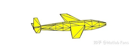
5.2 coordinate transformation and 3D graphics update
Matlab's Navigation Toolbox provides rich functions to realize coordinate transformation functions, such as eul2quat to realize the transformation from Euler angle to quaternion, quat2eul to realize the transformation from quaternion to Euler angle, and eul2tform to realize the transformation from Euler angle to coordinate transformation matrix.
The idea of updating 3D graphics is also very simple: first obtain the Euler angle or quaternion entered by the user, then use the above Matlab function to obtain the coordinate transformation matrix, then convert the aircraft drawing data from the body coordinate system to the ground coordinate system (equivalent to the drawing coordinate system) through the coordinate transformation matrix, and then use the set function to update the coordinate data of the aircraft graphic object, Form an animation effect.
5.3 about AppDesigner
This is the first time I have used AppDesigner to make GUI. I used to use GUIde. In general, AppDesigner has many rich functions, more convenient operation and relatively beautiful interface. The biggest feeling is:
- The App file is changed from m file + fig file in GUIde to a single mlapp file, which avoids the disharmony between m file and fig file, and it is more convenient to edit in the same interface;
- Multiple controls can share the same callback function. Here, the three slider modules share the same callback function, which can be directly selected in the callback function column.
6 source program download
For more details, welcome to download the source program.
If you have technical problems in Matlab / Simulink, please send an email to 944077462@qq.com Discussion. More Matlab/Simulink original information, welcome to WeChat official account: Matlab Fans
Demonstration of aircraft coordinate transformation using Matlab AppDesigner