Puzhong 51-Mononuclear-A2
STC89C52
Keil uVision V5.29.0.0
PK51 Prof.Developers Kit Version:9.60.0.0
Hard knowledge
Selected from V1.2 Development Strategies for Puzhong 51 Single-chip Computer
Introduction to Digital Tube
Digital tube is a semiconductor light emitting device, also known as LED digital tube, whose basic unit is light emitting diode.
The digital tube can be divided into seven segments and eight segments. Eight segments have one more LED unit, or one decimal point (DP), than seven segments. This decimal point can more accurately represent what the digital tube wants to display.
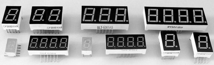
It can be divided into 1-bit, 2-bit, 3-bit, 4-bit, 5-bit, 6-bit, 7-bit digital tubes according to how many [8] can be displayed.
There are common anode digital tube and common cathode digital tube according to the connection mode of LED unit.
A common-anode digital tube is a digital tube that connects the anodes of all light-emitting diodes together to form a common anode (COM). The common-anode digital tube should connect COM to + 5V when it is used. When the cathode of a field light-emitting diode is at low level, the corresponding field will light up. When the cathode of a field is at high level, the corresponding field will not light up.
The common cathode digital tube refers to the digital tube that connects all the cathodes of the light emitting diodes together to form a common cathode (COM). The common cathode COM should be connected to the ground wire GND when the common cathode is used. When the anode of a field light emitting diode is at a high level, the corresponding field will light up. When the anode of a field is at a very low level, the corresponding field will not light up.
The physical picture of the tube with different digits is as follows:
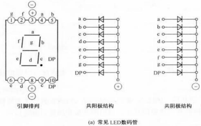
As you can see from the picture, the pins of a single digital tube are 10. It takes 7 segments to display an 8-word word, and there is another decimal point. So there are 8 small light-emitting diodes inside. Finally, there is a public end. Most manufacturers encapsulate 10 pins in order to package uniformly. The pins 3 and 8 are connected together.
The common end can be divided into common anode and common cathode, with the internal principle of common anode in the middle and the internal principle of common cathode in the right.
For a common cathode digital tube, the cathodes of its eight light-emitting diodes are all connected together inside the tube, so they are called "common cathode". Their anodes are independent and usually the cathode is grounded in the design of the circuit. When we add a high level to either of the anodes of the tube, the corresponding light-emitting diode lights up. If you want to show an 8 word and light the decimal point in the lower right corner, you can send a high level to all the eight anodes. If you want to show a 0 word, we can send a high level to all pins except for the low level to the g, dp, so that it will show a 0 word.
If you use Gongyin Digital Tube, you need to pay attention to increasing the driving current of the IO port of the single chip computer, because Gongyin Digital Tube is illuminated by the output current of the IO port of the single chip computer, but it is difficult for the I/O port of the single chip computer to output a stable and so large current, so when connecting the digital tube to the single chip, you need to add the driving circuit, you can use the pull-up resistance method or use a special digital tube to drive the chip. For example, 74HC573, 74HC245, etc. have a large output current and simple circuit interface.
All the anodes of the eight light-emitting diodes inside the common-anode digital tube are connected together. When the circuit is connected, the common end connects with the high level, so we need to send the low level to the cathode to light which light-emitting tube diode. This shows that the coding of the number is opposite to the coding of the common-cathode. When the light-emitting diode inside the digital tube is lit, it also needs more than 5mA of current. And the current should not be too large, otherwise the light-emitting diode will be burned out. Therefore, not only should the current of the digital tube be prevented from being too large, but also the current flowing through the digital tube should not be too large when it is concentrated in the single chip computer, otherwise the main chip will be damaged.
In general, common-anode digital tubes are more common, because the non-public end of the digital tube is often connected to the I/O of the IC chip, and the driving power of the IC chip is often relatively small. If a common-anode digital tube is used, its driving end is not public, which may be limited by the insufficient output current of the IC chip and dim display. Add a pull resistance or a triode to increase the drive capacity. However, the input current range of IC chips is large. So the advantage of using a common-anode digital tube is that the work of driving the tube is handed over to the public end (usually connected to the drive power). Increasing the power of the drive power is naturally much simpler than increasing the drive current at the I/O port of the IC chip. On the other hand, this can also reduce the load on the main chip.
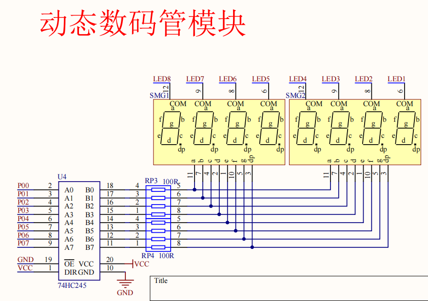
Introduction of Multidigit Digital Tube
A multi-digit digital tube is a digital tube in which two or more individual digital tubes are placed side by side in one. When many digits are in one, their internal common ends are independent, and the segment lines (a-dp) responsible for displaying what numbers are all connected together. The independent public ends can control which digit tube in one digit is lit. The connected segments can control what digits this digit tube lights up. The common ends are often called bit selection. The segment lines that connect together are called "segment selection". With these two lines, any number can be displayed by any digital tube controlled by a single chip computer and an external drive circuit.
Principle of Digital Tube Dynamic Display
When a multi-digit tube is used in a system, its "bit selection" is independently controlled, and the "segment selection" is connected. We can control which digits are on by the bit selection signal. At the same time, all digits displayed on the bit selected tube are always the same, because their segment selections are connected. The segment selection signals that are fed into all the digital tubes are the same, so they must display the same number. This display method of the digital tubes is called static display.
Dynamic display is achieved by reducing segment selection, separating bit selection, and changing segment selection data by using bit selection to select breaks at different times. For example, when the first digit tube is selected for the first time, data 0 is selected for the segment, and 1 is displayed when the second digit tube is selected for the next bit. In order for 0 to not disappear when displaying 1 (and indeed disappear), the first lighted 0 must be re-illuminated in a time not visible to the human eye. It is important to remember that the human eye normally recognizes movements that change more than 24 MS apart. That is, the difference in time between the next light of 0 must not be greater than 24ms. At this point, you will find that the digital tube lights up one bit to the right or left, forming a dynamic effect. A longer interval will show this directly.
Introduction of 74HC245 chip
74HC245 is a three-state output, eight-way signal transceiver that is mainly used in large-screen display and other consumer electronics products to increase driving power.
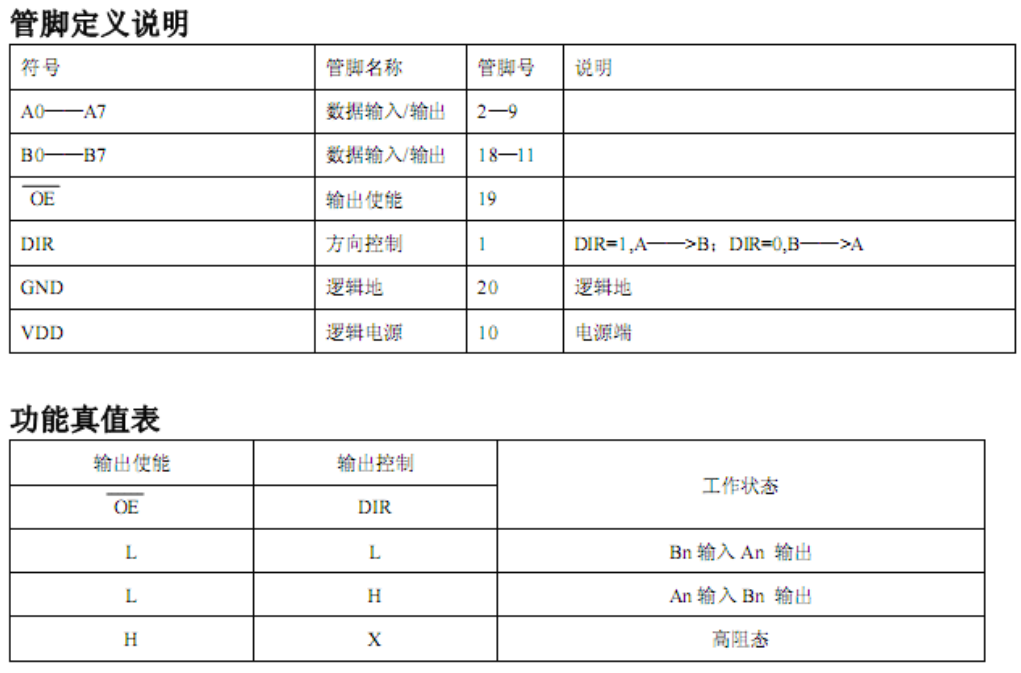
Give OE enable pin low level, DIR pin high level transmission direction is A->B output, DIR low level transmission direction is B->A, as to whether output high level or output low level depends on the state of input, if input is low level, output is low; The input is high and the output is high. If the OE enables the pin to be high, the output is high resistance regardless of whether the DIR pin is high or low.
The OE pin on the development board is connected with GND, the DIR pin is connected with VCC, and the transmission direction is A->B.
Introduction of 74HC138 Chip
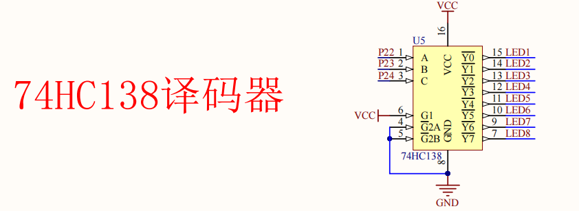
74HC138D is a three-channel input and eight-channel output decoder, which is mainly used in consumer electronics products.
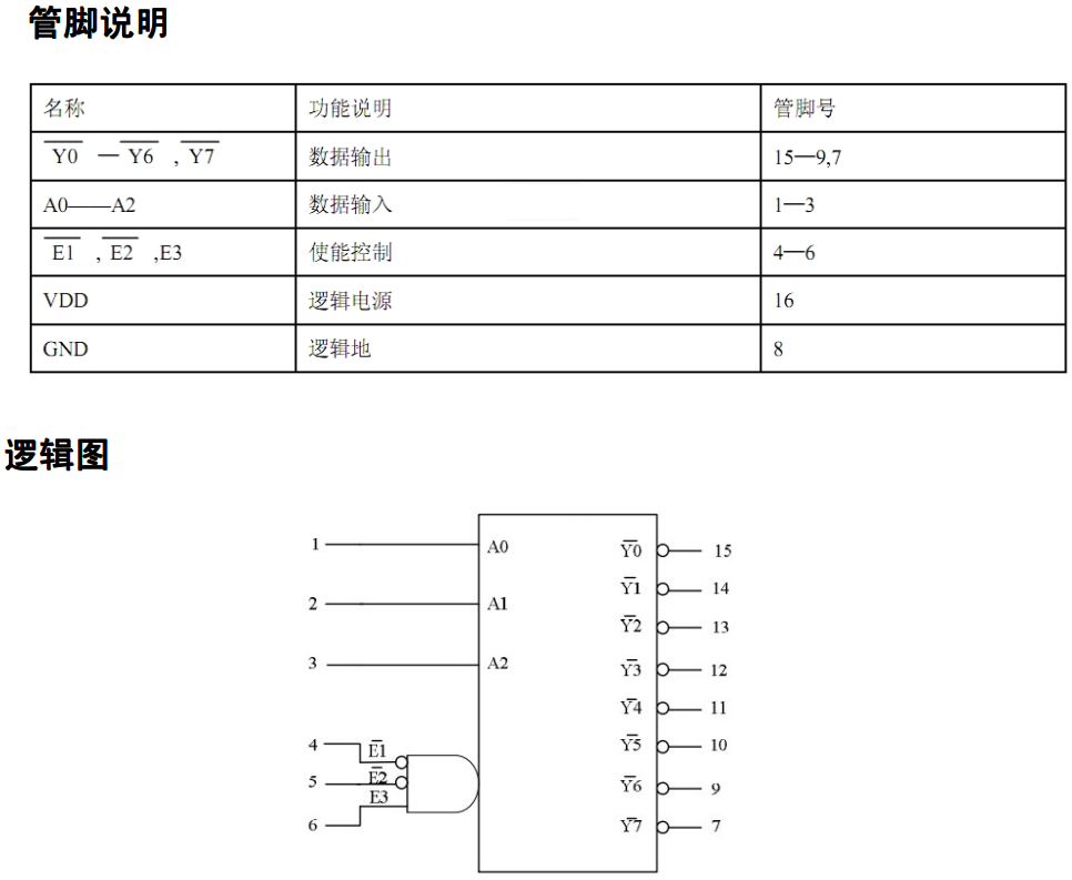
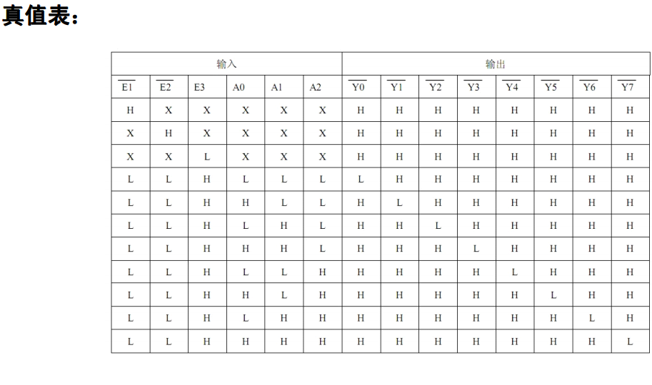
Enable E1, E2 pins to have low level, E3 pins to have high level. As to which pin output effective level (low level), it depends on the level status of A0, A1, A2 input pins. If A0, A1, A2 are all low, Y0 outputs a valid level (low level) and the other pins a high level. If A0 is high, A1, A2 are low, Y1 outputs a valid level (low level) and the other pins a high level.
The inputs A0, A1, A2 are equivalent to 3-bit binary numbers, A0 is low, A1 is secondary high, and A2 is high. Which output level of Y0~Y7 is valid depends on the decimal value of the input binary. For example, the input is 101 (A2, A1, A0), and its corresponding decimal number is 5, so Y5 outputs a valid level (low level).
On-board combat
See stdint.h [Quick Start Guide for 51 Single-chip Microcomputer] 1: Basic Knowledge and Engineering Creation
Source code
Tube.c
#include <REGX52.H>
#include "intrins.h"
#include "stdint.h"
#include "Tube.h"

#define Tube_Port P0

sbit P74138_A0 = P2^2;
sbit P74138_A1 = P2^3;
sbit P74138_A2 = P2^4;

//Display delay 400us @11.0592MHz
void LED_Tube_Delay()
{
	unsigned char i;

	_nop_();
	i = 181;
	while (--i);
}

//Bit Selection
void F74138(uint8_t num)
{
	num &= 7;
	P74138_A0 = (num & 1);
	P74138_A1 = (num & 2) >> 1;
	P74138_A2 = (num & 4) >> 2;
}

code uint8_t Tube_Codes_0ToF[] =
{
	Tube_Code_0,
	Tube_Code_1,
	Tube_Code_2,
	Tube_Code_3,
	Tube_Code_4,
	Tube_Code_5,
	Tube_Code_6,
	Tube_Code_7,
	Tube_Code_8,
	Tube_Code_9,
	Tube_Code_A,
	Tube_Code_b,
	Tube_Code_C,
	Tube_Code_d,
	Tube_Code_E,
	Tube_Code_F
};

//Display decimals in scientific counting
void Display_Double(double Num)
{
	uint8_t i = 0;
	int8_t pow = 0;
	uint8_t DisplayNum = 0;
	double Num_clone;
	char Tube_Double_Buffer[8] = {0};

	if (Num < 0)
	{
		Tube_Double_Buffer[7] = Tube_Code_Negative_Sign;
		Num = -Num;
	}
	if (Num < 1e-8)													//Treat as 0
	{
		for(i = 0; i < 7; ++i)
			Tube_Double_Buffer[i + 1] = Tube_Code_NULL;
		Tube_Double_Buffer[0] = Tube_Codes_0ToF[0];
	}
	else if (Num > 1e8)												//As an overflow, Error
	{
		Tube_Double_Buffer[6] = Tube_Code_NULL;
		Tube_Double_Buffer[5] = Tube_Code_E;
		Tube_Double_Buffer[4] = Tube_Code_r;
		Tube_Double_Buffer[3] = Tube_Code_r;
		Tube_Double_Buffer[2] = Tube_Code_o;
		Tube_Double_Buffer[1] = Tube_Code_r;
		Tube_Double_Buffer[0] = Tube_Code_NULL;
	}
	else
	{
		Num_clone = Num;
		if(Num_clone < 1000)
		{
			while(Num_clone < 1000)
			{
				Num_clone *= 10;
				++pow;
			}
			pow = 3-pow;											//Exponential
		}
		else
		{
			pow = 3;
			while(Num_clone > 9999)
			{
				Num_clone /= 10;
				++pow;												//Exponential
			}
		}
		Num_clone /= 10;
		for(i = 0; i < 3; ++i)										//Three Significant Digits
		{
			DisplayNum = (int)(Num_clone + (i == 0) * 0.5) % 10;	//Last Round
			Tube_Double_Buffer[i + 4] = Tube_Codes_0ToF[DisplayNum];
			Num_clone /= 10;
		}
		Tube_Double_Buffer[6] |= Tube_Code_Dot;						//Complementary Decimal Point
		Tube_Double_Buffer[3] = Tube_Code_E;

		if(pow < 0)
		{
			Tube_Double_Buffer[2] = Tube_Code_Negative_Sign;		//Exponential sign is negative
			pow = -pow;
		}
		for(i = 0; i < 2; ++i)
		{
			DisplayNum = pow % 10;
			Tube_Double_Buffer[i] = Tube_Codes_0ToF[DisplayNum];	//index
			pow /= 10;
		}
	}
	for(i = 0; i < 8; ++i)
	{
		Tube_Port = Tube_Code_NULL;									//Close Bit Selection
		F74138(i);
		Tube_Port = Tube_Double_Buffer[i];							//display
		LED_Tube_Delay();
	}
	return;
}

//Show Integers
void Display_Int(int32_t Num)
{
	uint8_t i = 0;
	uint8_t DisplayNum = 0;
	char Tube_Double_Buffer[8] = {0};
	if(Num >= 10000000 || Num <= -10000000)
	{
		Display_Double((double)Num);							//Exponential output
		return;
	}
	else
	{
		if(Num < 0)
		{
			Tube_Double_Buffer[7] = Tube_Code_Negative_Sign;	//Minus sign
			Num = -Num;
		}
		for(i = 0; i < 7; ++i)
		{
			DisplayNum = Num % 10;
			if(Num == 0 && i != 0)
				Tube_Double_Buffer[i] = Tube_Code_NULL;
			else
				Tube_Double_Buffer[i] = Tube_Codes_0ToF[DisplayNum];
			Num /= 10;
		}
		for(i = 0; i < 8; ++i)
		{
			Tube_Port = Tube_Code_NULL;					//Close Bit Selection
			F74138(i);
			Tube_Port = Tube_Double_Buffer[i];			//display
			LED_Tube_Delay();
		}
		return;
	}
}

//Display Numbers
void Display_Num(double Num)
{
	if(Num == (int32_t)Num)
		Display_Int((int32_t)Num);
	else
		Display_Double(Num);
	return;
}
Tube.h
#ifndef TUBE_H_
#define TUBE_H_

#define Tube_Code_NULL 0x00

#define Tube_Code_0 0x3f
#define Tube_Code_1 0x06
#define Tube_Code_2 0x5b
#define Tube_Code_3 0x4f
#define Tube_Code_4 0x66
#define Tube_Code_5 0x6d
#define Tube_Code_6 0x7d
#define Tube_Code_7 0x07
#define Tube_Code_8 0x7f
#define Tube_Code_9 0x6f

#define Tube_Code_A 0x77
#define Tube_Code_b 0x7c
#define Tube_Code_C 0x39
#define Tube_Code_c 0x58
#define Tube_Code_d 0x5e
#define Tube_Code_E 0x79
#define Tube_Code_F 0x71
#define Tube_Code_G 0x3d
#define Tube_Code_H 0x76
#define Tube_Code_I 0x30
#define Tube_Code_i 0x10
#define Tube_Code_J 0x0e
#define Tube_Code_K	0x7a
#define Tube_Code_L 0x38
#define Tube_Code_M 0x55
#define Tube_Code_n	0x54
#define Tube_Code_o 0x5c
#define Tube_Code_P 0x73
#define Tube_Code_q 0x67
#define Tube_Code_r 0x50
#define Tube_Code_S 0x64
#define Tube_Code_t 0x78
#define Tube_Code_U	0x3e
#define Tube_Code_u 0x1c
#define Tube_Code_v 0x62
#define Tube_Code_W 0x6a
#define Tube_Code_X 0x36
#define Tube_Code_y 0x6e
#define Tube_Code_Z 0x49

#define Tube_Code_Dot 0x80
#define Tube_Code_Negative_Sign 0x40

void Display_Int(int32_t Num);
void Display_Double(double Num);
void Display_Num(double Num);

#endif
main.c
#include <REGX52.H>
#include "intrins.h"
#include "stdint.h"
#include "Tube.h"
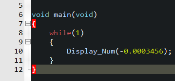
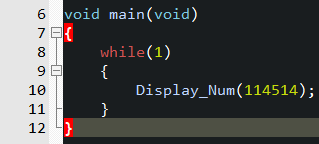
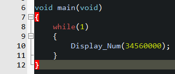
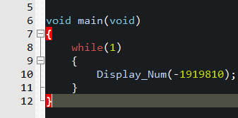
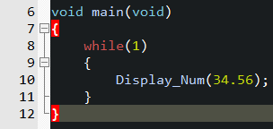
void main(void)
{
while(1)
{
Display_Num(114514);
}
}
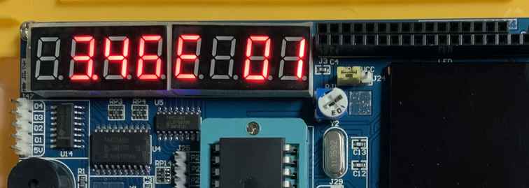
Effect
Show Integers
Positive number
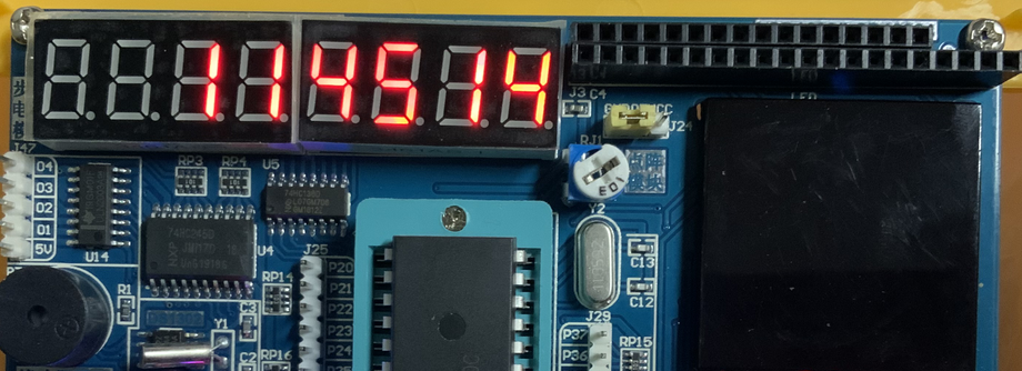
Larger Number
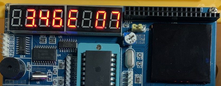
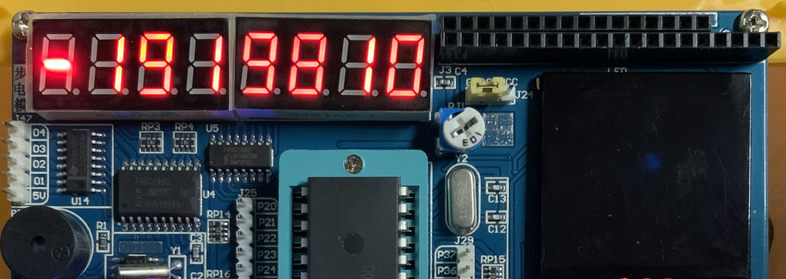
negative
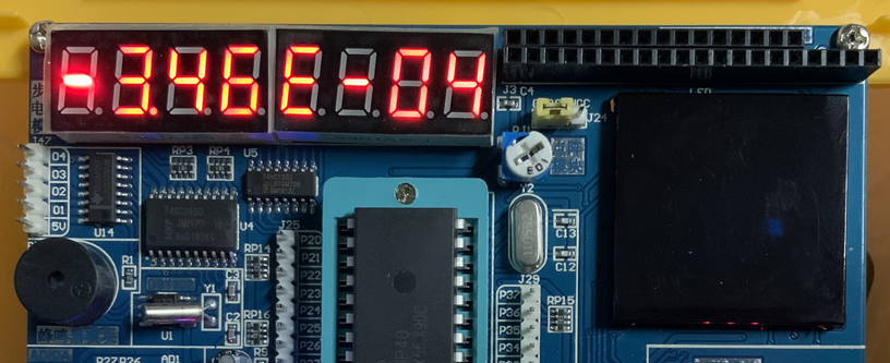
Display decimals (keep three significant digits)
Positive number
negative