1. The organization structure of the packets received by RTE? MBUF, RTE? MemPool and network card in memory

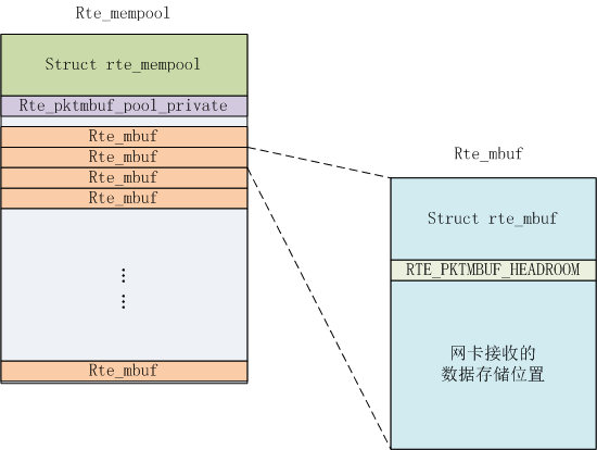
When the RTE? MemPool? Create() function is called to create the RTE? MemPool, it specifies how many RTE? Mbuffs are requested and the size of ELT? Size in each RTE? MBUF. elt_size is the pre allocated memory size for the packets received by the network card. This memory block is the actual storage area of rte_mbuf - > pkt.data. See the figure above for details.
In the applied RTE MemPool memory block, struct RTE MemPool data structure is stored first, followed by RTE pktmbuf pool private data, followed by N RTE MBUF memory blocks.
In each RTE MBUF memory, struct RTE MBUF data results are also stored in the front, followed by RTE pktmbuf headroom, and the data received by the actual network card is as follows:
struct rte_mbuf *m = _m;
    uint32_t buf_len = mp->elt_size - sizeof(struct rte_mbuf);

    RTE_MBUF_ASSERT(mp->elt_size >= sizeof(struct rte_mbuf));

    memset(m, 0, mp->elt_size);

    /* start of buffer is just after mbuf structure */
    m->buf_addr = (char *)m + sizeof(struct rte_mbuf);
    m->buf_physaddr = rte_mempool_virt2phy(mp, m) +
            sizeof(struct rte_mbuf);
    m->buf_len = (uint16_t)buf_len;

    /* keep some headroom between start of buffer and data */
    m->pkt.data = (char*) m->buf_addr + RTE_MIN(RTE_PKTMBUF_HEADROOM, m->buf_len);

    /* init some constant fields */
    m->type = RTE_MBUF_PKT;
    m->pool = mp;
    m->pkt.nb_segs = 1;
    m->pkt.in_port = 0xff;
2. How the data received by the network card is stored in RTE? MBUF
Take the e1000 network card as an example, when the network card is initialized, call eth ﹣ IGB ﹣ Rx ﹣ init() to initialize the packet receiving queue of the network card. The data results of each receiving queue are as follows:
/**
 * Structure associated with each RX queue.
 */
struct igb_rx_queue {
    struct rte_mempool  *mb_pool;   /**< mbuf pool to populate RX ring. */
    volatile union e1000_adv_rx_desc *rx_ring; /**< RX ring virtual address. */
    uint64_t            rx_ring_phys_addr; /**< RX ring DMA address. */
    volatile uint32_t   *rdt_reg_addr; /**< RDT register address. */
    volatile uint32_t   *rdh_reg_addr; /**< RDH register address. */
    struct igb_rx_entry *sw_ring;   /**< address of RX software ring. */
    struct rte_mbuf *pkt_first_seg; /**< First segment of current packet. */
    struct rte_mbuf *pkt_last_seg;  /**< Last segment of current packet. */
    uint16_t            nb_rx_desc; /**< number of RX descriptors. */
    uint16_t            rx_tail;    /**< current value of RDT register. */
    uint16_t            nb_rx_hold; /**< number of held free RX desc. */
    uint16_t            rx_free_thresh; /**< max free RX desc to hold. */
    uint16_t            queue_id;   /**< RX queue index. */
    uint16_t            reg_idx;    /**< RX queue register index. */
    uint8_t             port_id;    /**< Device port identifier. */
    uint8_t             pthresh;    /**< Prefetch threshold register. */
    uint8_t             hthresh;    /**< Host threshold register. */
    uint8_t             wthresh;    /**< Write-back threshold register. */
    uint8_t             crc_len;    /**< 0 if CRC stripped, 4 otherwise. */
    uint8_t             drop_en;  /**< If not 0, set SRRCTL.Drop_En. */
};
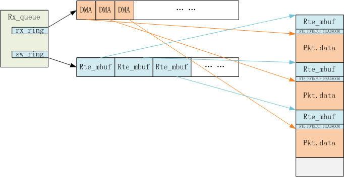
We only focus on two of the member variables, RX ring and SW ring. RX ring records the array of union E1000 adv RX desc. Each union E1000 adv RX desc specifies the DMA address to which the network card receives the data. After receiving the data, the network card writes the data directly. The SW ring array records each specific RTE MBUF address. The mapped DMA address of each RTE MBUF is stored in the union E1000 adv RX desc data structure of the RX ring queue. RTE > buf > phyaddr + RTE > pkt MBUF > headroom points to the address of RTE > pkt.data. At this time, the packet receiving queues of the network card are associated with RTE buf, RTE buf - > pkt.data. The details are as follows:
static int
igb_alloc_rx_queue_mbufs(struct igb_rx_queue *rxq)
{
    struct igb_rx_entry *rxe = rxq->sw_ring;
    uint64_t dma_addr;
    unsigned i;

    /* Initialize software ring entries. */
    for (i = 0; i < rxq->nb_rx_desc; i++) {
        volatile union e1000_adv_rx_desc *rxd;
        struct rte_mbuf *mbuf = rte_rxmbuf_alloc(rxq->mb_pool);

        if (mbuf == NULL) {
            PMD_INIT_LOG(ERR, "RX mbuf alloc failed "
                "queue_id=%hu\n", rxq->queue_id);
            return (-ENOMEM);
        }
        dma_addr =
            rte_cpu_to_le_64(RTE_MBUF_DATA_DMA_ADDR_DEFAULT(mbuf));
        rxd = &rxq->rx_ring[i];
        rxd->read.hdr_addr = dma_addr;
        rxd->read.pkt_addr = dma_addr;
        rxe[i].mbuf = mbuf;
    }

    return 0;
}
After the network card receives the data, it writes the data to the DMA address specified by RX ring. In fact, it writes the data to each rte_mbuf - > pkt.data. When calling rte_eth_rx_burst(), the application takes E1000 network card as an example, and finally calls eth_igb_recv_pkts(), which extracts rte_mbuf from the sw_ring array from every packet queue, then replaces the application of new rte_mbuf to rx_ring, replaces the rte_mbuf address, union e1000_adv_rx_desc, sw_ring and Union address. As shown in the following diagram:


