Program design of temperature value display of DS18B20
I Characteristics of DS1820 single line digital thermometer
• unique single line interface requires only one port pin for communication
• simple multipoint distribution applications
• no external components required
• power supply via data line
• zero standby power consumption
• temperature measurement range: - 55 ~ + 125 ℃, increasing by 0.5 ℃. Fahrenheit device - 67~+2570F, increasing by 0.90F
• the temperature is read out in 9 digits
• temperature digital conversion time 200ms (typical value)
• user definable non-volatile temperature alarm settings
• the alarm search command identifies and flags devices that exceed the program limit temperature (temperature alarm condition)
• applications include temperature control, industrial systems, consumer goods, thermometers or any thermal sensing system
II ROM operation instruction
Read ROM [33H]
Match ROM [55h]
Skip ROM [CCH]
Search ROM [F0H]
Alarm search [ECH]
III Memory operation command
Write scratchpad [4EH]
Read scratchpad [BEH]
Copy scratchpad [48H]
Convert temperature [44H]
Recall EPROM [B8H]
Read power supply [B4H]
Don't say much, just go to the code.
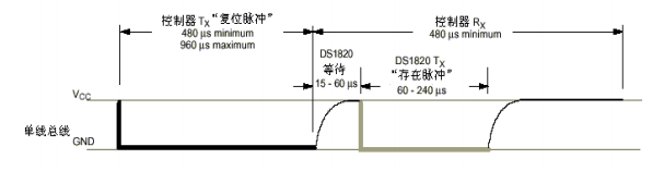
1. Initialize sub functions
After the host pulls the data line DQ down 480us, release the bus, detect whether the DQ is low level within 60 ~ 240 us after 15 ~ 60 us delay, and then delay 240us to ensure the integrity of the starting sequence.
bit init_ds18b20(void)
{
  	bit initflag = 0;

  	DQ = 1;             //Host pull down bus
  	Delay_OneWire(12);
  	DQ = 0;             //Host release bus

  	Delay_OneWire(80); // Delay greater than 480us
  	DQ = 1;
  	Delay_OneWire(10);  // 14
  	initflag = DQ;     // initflag equal to 1 initialization failed
  	Delay_OneWire(5);   //Proper delay to ensure complete timing

  	return initflag;
}
2. Write a byte to DS18B20 through single bus
Note: the low order of transmission data is in front
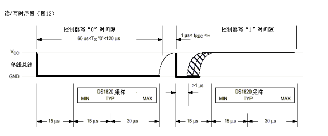
At the beginning of the write cycle, the host first pulls the bus lower than 1us, indicating the beginning of the write cycle.
If the host writes 0, continue to pull the low level for at least 60us until the end of the write cycle, and then release the bus to high level
If the host writes 1, after pulling down the bus level 1us, release the bus to high level until the end of the write cycle.
void Write_DS18B20(unsigned char dat)
{
	unsigned char i;
	for(i=0;i<8;i++)
	{
		DQ = 0;				    //The host pulls down the bus and starts writing
		DQ = dat&0x01;		    //The low bit of data transmission goes before the lowest set and delay
		Delay_OneWire(5);	    //Give the slave time to get to this position
		DQ = 1;				    //Release the bus after sending the current bit
		dat >>= 1;			    // Prepare for the next one
		                        //Note: move left or right, first or last
	}
	Delay_OneWire(5);

}
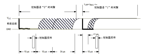
3. Read a byte from DS18B20
At the beginning of the read cycle, the host first pulls down the bus by more than 1us, and then releases the bus. After the host releases the bus:
If the host sends 0, continue to pull down the bus and keep at least 15us from the reading cycle, and then release the bus to high level.
If the host sends 1, it will not pull down the bus after the host releases the bus, which is a high level.
The host must detect the bus level within 15us at the beginning of the read cycle
unsigned char Read_DS18B20(void)	//Call returns the bytes read
{
	unsigned char i;			    //If you can use local variables, you don't need global variables
	unsigned char dat;
//	unsigned char index = 0;

	for(i=0;i<8;i++)		    //Read one at a time
	{
		DQ = 0;				   //The host pulls down the bus and starts reading the current bit for at least one microsecond
		dat >>= 1;			   //Displacement and delay, the first right displacement has no effect
		DQ = 1; 			   //Host release bus
	   	Delay_us();			   //The delay makes the slave get a response

		if(DQ)  			   //If 1 is detected or written as (DQ==1)
		{
			dat |= 0x80;	   //Set dat to the highest 1000
		}
		Delay_OneWire(5);		//Appropriate delay, degree cycle at least 60US
	}
	return dat;					//Send the received bytes back to the caller
}
4.DS18B20 temperature acquisition program
unsigned char rd_temperature(void)
{
   char temp,flag,xiaoshu1,xiaoshu2;
   int low,high;
   init_ds18b20();
   Write_DS18B20(0xcc);			//Skip writing rom instruction
   Write_DS18B20(0x44);			//Start temperature conversion
   Delay_OneWire(50);

   init_ds18b20();
   Write_DS18B20(0xcc);			//Skip writing rom instruction
   Write_DS18B20(0xbe);			//Start temperature conversion 	 The single bus must be strongly pulled up by 10us (at most) during the conversion
   Delay_OneWire(50);

   low=Read_DS18B20();  	 //In the transmission process, the low eight bit transmission is followed by the high eight bit transmission
   high=Read_DS18B20();

   temp=low/16+high*16 ;  //The temperature is assembled into bytes
                          //Equivalent to temp = (low > > 4) | (high < < 4) 	; Shift the low byte to the right and shift the high byte to the left
   if(temp>=127)		  //If the sign bit is 1, the result is negative. The flag bit is judged here
   {
 		flag = 1; 		 //If the sign bit is 1, the temperature is negative
		temp = ~temp+1;  //Convert complement to original code

   }
   xiaoshu1 = (low&0x0f)*10/16;       //Take the first decimal place of temperature
   xiaoshu2 = (low&0x0f)*100/16%10;   //Take the second decimal place of temperature
   //Another way of writing
   /*
   xiaoshu1 = (low&0x0f)*625/1000;
   xiaoshu2 = (low&0x0f)*625/100%10;
   */
   return temp;
}
/CCH skip rom Instruction 1100 is written 0011 0011
//When BEH is written, the segment code sent into the register is 0111 1101 before the low bit and 1011 1110 after the high bit
// 8421 a 10 1010  b 11 1011   c 12 1100   d 13 1101   e 14 1110   f 15 1111
5. Delay subfunction
void Delay_OneWire(unsigned int t)
{
	unsigned char i;
	while(t--){
		for(i=0;i<12;i++);
	}
}

void Delay_us(void)
{
	unsigned char i;
	i = 30;
	while (--i);
}
I hope it can help you.