sketch:
DS18B20 temperature sensor on the Blue Bridge Cup board, the communication mode is single bus communication (1-wire); At the same time, in the data package of the Blue Bridge Cup competition, a library file about DS18B20 (onewire.h, onewire.c) is provided, which has three functions: sensor reset [bit init_ds18b20(void)], write byte [void Write_DS18B20(unsigned char dat)] and read byte [unsigned char Read_DS18B20(void)]. Therefore, we do not necessarily need to make the timing of I2C very clear, but only need to understand the basic operation process of DS18B20.
Information available according to the chip data manual provided:
-
DS18B20 uses single bus protocol to communicate with the host. Under the condition of single line port, ROM operation protocol must be established before memory and control operation.
-
The configuration register allows the user to set the resolution of temperature digital conversion to 9, 10, 11 or 12 bits. The core function of DS18B20 is direct digital temperature sensor. The resolution of the temperature sensor can be configured as 9, 10, 11 or 12 bits by the user, corresponding to the increments of 0.5 ℃, 0.25 ℃, 0.125 ℃ and 0.0625 ℃ respectively. The default resolution at power on is 12 bits (i.e. the accuracy is 0.0625 ℃).
-
The protocol for accessing DS18B20 through single line bus port is as follows:
• initialization
• ROM operation commands
• memory operation commands
• execution / data
ROM operation command:
| Name (register address) | effect | other |
|---|---|---|
| Search ROM(F0H) | The host identifies the ROM codes of all slaves on the bus | |
| Read ROM(33H) | The host reads the 64 bit ROM code of the slave | |
| Match ROM(55H) | Matching 64 bit ROM commands | |
| Skip ROM(CCH) | The host uses this command to address all devices on the bus at the same time, and the slave data can be read without sending the 64 bit rom code of the device | It is suitable for the design of CT107D development board and there is only one device on the bus |
| Alarm Search(ECH) | The host determines whether there is an alarm in DS18B20 during the last temperature conversion | Rarely used |
The host can use the Skip ROM command to address all devices on the bus at the same time without sending any ROM code information. For example, the host can make all DS18B20 on the bus perform temperature conversion at the same time by issuing the Skip ROM command and then issuing the Convert T [44h] function command.
Note that the Skip ROM command applies when there is a slave on the bus. In this case, the host can read the slave data without sending the 64 bit ROM code of the device, thus saving time.
Memory operation command
| Operation command name (register address) | describe |
|---|---|
| Convert Temperatures(44H) | This command initiates a temperature conversion. After conversion, the generated thermal data is stored in the 2-byte temperature register of the temporary storage memory |
| Write Scratchpad (4EH) | This command allows the host to write 3 bytes of data to the register of DS18B20. |
| Read Scratchpad (BEH) | This command allows the host to read the data of the register. Data transmission starts from the least significant bit of byte 0 (starting from the lower octet) and continues through the register until the upper octet is read. |
Temperature conversion and temperature acquisition
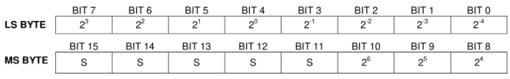
Temperature register format:
When it is necessary to perform temperature measurement, the bus controller must issue a temperature conversion command. After that, the generated temperature data is stored in the temperature register of the high-speed register in the form of two bytes, and the DS18B20 continues to remain in the waiting state. The single-chip microcomputer can read the data through the single-line interface. When reading, the low order is in the front and the high order is in the back.
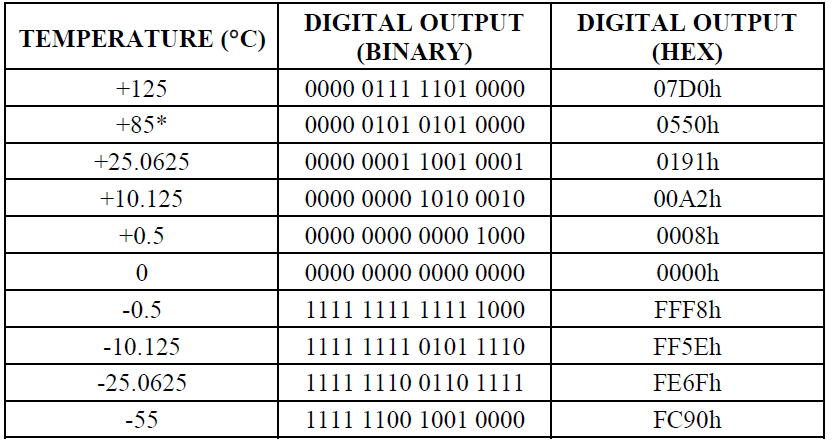
In the following table, the upper 5 bits S are extended symbol bits. When S=0, it means that the measured temperature value is positive, and the binary bit can be directly converted to decimal; When S=1, it means that the measured temperature value is negative. First change the complement into the original code, and then calculate the decimal value.
After the DS18B20 performs a temperature conversion, the temperature value is compared to the user-defined two's complex alarm trigger values stored in the 1-byte th and TL registers (see Figure 3) The sign bit (S) indicates if the value is positive or negative: for positive numbers S = 0 and for negative numbers S = 1.
Specific operation of obtaining temperature
Basic operation of reading DS18B20 temperature once:
<1> Reset and initialize DS18B20.
<2> Write 0xCC command to DS18B20 and skip ROM.
<3> Write 0x44 command to DS18B20 to start temperature conversion.
<4> Wait for the temperature conversion to complete.
<5> Reset and initialize DS18B20.
<6> Write 0xCC command to DS18B20 and skip ROM.
<7> Write 0xBE command to DS18B20 and start reading the temperature data in the register
<8> Store the read temperature data of the upper eight bits and the upper eight bits into the corresponding variables
<9> Reset and initialize DS18B20.
Code example of completely reading temperature data once:
    Init_DS18B20();			//Reset and initialize DS18B20.
    Write_DS18B20(0xCC);	//Skip ROM and use only when there is only one slave on the bus
    Write_DS18B20(0x44);	//Perform temperature conversion
    Init_DS18B20();			//Reset and initialize DS18B20.
    Write_DS18B20(0xCC);	//Skip ROM and use only when there is only one slave on the bus
    Write_DS18B20(0xBE);	//Start reading the temperature data in the register in the order from the lower eight bits to the upper eight bits
    LSB = Read_DS18B20();	//Store the lower eight bits into the LSB variable
    MSB = Read_DS18B20();	//Store the upper eight bits into the MSB variable
    Init_DS18B20();			//Reset and initialize DS18B20.
Temperature data processing and nixie tube display
Actual temperature calculation (positive temperature value) according to the variable of stored temperature data:
unsigned int Digital_Output,Decimals,Integer;
Digital_Output = MSB << 8 | LSB 		//Move the upper eight bits to the left by 8 bits and add the lower eight bits to form a complete 16 bit temperature data
if(Digital_Output & 0xF800 == 0X0000)
{
		Integer  = (Digital_Output >>4)* 100;			//Extract the integer part and multiply by 100
		Decimals =  (LSB & 0x0f) * 0.0625*100;	//The extracted fraction is multiplied by the precision and then multiplied by 100
		Digital_Output =Integer+Decimals;
}
Data processing when decimals need to be retained (nixie tube display):
For example: we want to display 15.34
step:
1>Will 15.34*100
2>Each bit is extracted using 1534
1534/1000 = 1;
1534/100%10 = 5;
1534/10%10 = 3;
1534%10 = 4;
3>Display each digit obtained on the nixie tube//Remember that when the nixie tube displays, 5 is a font with a decimal point >
Complete project code example:
#include "reg52.h"
#include "onewire.h" 	// Single bus driver header file in reference

unsigned int T_dat; //Define a temperature variable
/*The nixie tube displays the required word code*/
unsigned char SMG_NoDot[19] = {0xc0, 0xf9, 0xa4, 0xb0, 0x99, 0x92, 0x82, 0xf8, 0x80, 0x90, 0x88, 0x80, 0xc6, 0xc0, 0x86, 0x8e, 0xbf, 0x7f, 0xff}; //0-9,A-F,'-','.'
unsigned char code SMG_IsDot[10] = {0x40, 0x79, 0x24, 0x30, 0x19, 0x12, 0x02, 0x78, 0x00, 0x10};

void Delay500us();
void Read_Temperature();	//Read the temperature once from DS18B20 and process the temperature as a function
void Display_Temperature(unsigned int dat); //Digital tube display of temperature data, with two decimal places reserved
void Digital_Tube(unsigned char Position, unsigned char Typeface);	//Nixie tube single character display function

void main()
{
    while (1)
    {
        Read_Temperature();
        Display_Temperature(T_dat);
    }
}

void Delay500us()       //@12.000MHz
{
    unsigned char i, j;

    i = 6;
    j = 211;
    do
    {
        while (--j);
    }
    while (--i);
}

void Digital_Tube(unsigned char Position, unsigned char Typeface)   //Position is the position of the nixie tube (from left to right, starting with 0), and Typeface is the displayed word
{
    unsigned char Bit[8] = {0x01, 0x02, 0x04, 0x08, 0x10, 0x20, 0x40, 0x80};
    P2 = P2 & 0x1f | 0xc0;
    P0 = Bit[Position];
    P2 = P2 & 0x1f | 0xe0;
    P0 = Typeface;
    Delay500us();
    P0 = 0XFF;
    P2 = P2 & 0x1f ;    //Nixie tube shadow elimination
}

void Display_Temperature(unsigned int dat)	//Digital tube display of temperature data, with two decimal places reserved
{
    Digital_Tube(7, SMG_NoDot[dat % 10]);
    Digital_Tube(6, SMG_NoDot[dat / 10 % 10]);
    Digital_Tube(5, SMG_IsDot[(dat / 100) % 10]);
    Digital_Tube(4, SMG_NoDot[(dat / 1000) % 10]);

	/*All digital tubes are extinguished, and the shadow is eliminated*/
    P2 = P2 & 0x1f | 0xc0;
    P0 = 0XFF;
    P2 = P2 & 0x1f | 0xe0;
    P0 = 0XFF;
}

void Read_Temperature()	//Read the temperature once from DS18B20 and process the temperature as a function
{
    unsigned char LSB, MSB;
	unsigned int Decimals,Integer;	//Define local variables, integers, decimals

    Init_DS18B20();			//Reset and initialize DS18B20.
    Write_DS18B20(0xCC);	//Skip ROM and use only when there is only one slave on the bus
    Write_DS18B20(0x44);	//Perform temperature conversion
    Init_DS18B20();			//Reset and initialize DS18B20.
    Write_DS18B20(0xCC);	//Skip ROM and use only when there is only one slave on the bus
    Write_DS18B20(0xBE);	//Start reading the temperature data in the register in the order from the lower eight bits to the upper eight bits
    LSB = Read_DS18B20();	//Store the lower eight bits into the LSB variable
    MSB = Read_DS18B20();	//Save variable to MSB high
    Init_DS18B20();			//Reset and initialize DS18B20.

    T_dat = 0x0000;			//Data initialization
    T_dat = MSB << 8 | LSB;	//Merge the lower eight bits and the upper eight bits

    if ((T_dat & 0xf800) == 0x0000)		//Judge whether it is positive
    {
		Integer  = (T_dat >>4)* 100;			//Extract the integer part and multiply by 100
		Decimals =  (LSB & 0x0f) * 0.0625*100;	//The extracted fraction is multiplied by the precision and then multiplied by 100
		T_dat=Integer+Decimals;		//Add the integral part of 100 times to the decimal part of 100 times
    }
}
DS18B20 Blue Bridge Cup document and the whole project document download: