More exchanges, welcome tiktok, 81849645041
target
The slave device EEPROM can read and write data.
principle
EEPROM is a memory that does not lose data after power failure. It is often used to store some configuration information for loading when the system is powered on again. The most commonly used communication mode of EEPROM chip is I2C protocol.
The model of EEPROM chip on STM32F4 development board is 24C02. The total capacity of the chip is 256 bytes. The chip is connected to the outside through IIC bus.
EEPROM hardware connection diagram
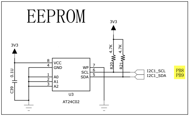
The SCL and SDA pins of EEPROM chip (model: AT24C02) in this experimental board are connected to the I2C pin corresponding to STM32. Combined with the pull-up resistance, they constitute the I2C communication bus, which interact through the I2C bus. The device address of EEPROM chip has 7 bits in total, of which the upper 4 bits are fixed as 1010 b, and the lower 3 bits are determined by the level of A0/A1/A2 signal line. R/W in the figure is the read-write direction bit, which is independent of the address.
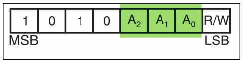
According to our connection here, A0/A1/A2 are all 0, so the 7-bit device address of EEPROM is 1010 000b, i.e. 0x50. In I2C communication, the address is often connected with the read-write direction to form an 8-digit number, and when the R/W bit is 0, it indicates the write direction. Therefore, add the 7-bit address, and its value is "0xA0", which is often referred to as the "write address" of I2C equipment; When the R/W bit is 1, it indicates the reading direction, plus the 7-bit address, and its value is "0xA1", which is often called "read address".
There is also a WP pin in the EEPROM chip, which has the write protection function. When the pin level is high, it is prohibited to write data. When the pin level is low, it can write data. It is directly grounded here and the write protection function is not used.
prepare
MDK5 development environment.
STM32F4xx HAL library.
STM32F407 development board.
STM32F4xx reference manual.
STM32F4xx data book.
Circuit schematic diagram of STM32F407 development board.
step
- Use IIC communication experiment to read and write EEPROM, and add macros and functions to the header file.
#ifndef __BSP_HARD_IIC_H
#define __BSP_HARD_IIC_H

#include "stm32f4xx.h"

#define u8 uint8_t
#define u16 uint16_t
#define u32 uint32_t

// I2C clock
#define I2C_Speed 400000
//  The I2C address of STM32 itself, as long as it is different from the I2C device address of STM32 plug-in
#define I2C_OWN_ADDRESS7 0X0A

#define ADDR_24LCxx_Write 0xA0 // EEPROM device address write direction
#define ADDR_24LCxx_Read 0xA1 // EEPROM device address read direction

void IIC_MODE_Init(void); // I2C mode initialization
u8 I2C_EE_IsDeviceReady(u8 DevAddress); // Check whether EEPROM equipment is ready

u8 I2C_EE_ByteWrite(u8* TxData,u8 DevAddress,u8 WriteAddr); // Write a byte
u8 I2C_EE_ByteRead(u8* RxData,u8 DevAddress,u8 WriteAddr); // Read a byte

u8 I2C_EE_NByteWrite(u8* TxData,u8 DevAddress,u8 WriteAddr,u8 DataSize); // Write multiple bytes
u8 I2C_EE_NByteRead(u8* RxData,u8 DevAddress,u8 ReadAddr,u8 DataSize); // Read multiple bytes
#endif
- Implement EEPROM read-write function. Single byte read / write and multi byte read / write. It mainly calls HAL library function HAL_I2C_Mem_Write() write data, HAL_I2C_Mem_Read() reads data.
HAL_I2C_Mem_Write() function parsing:
HAL_StatusTypeDef HAL_I2C_Mem_Write(I2C_HandleTypeDef *hi2c, uint16_t DevAddress, uint16_t MemAddress, uint16_t MemAddSize, uint8_t *pData, uint16_t Size, uint32_t Timeout)
/**
  * @brief  Writes a large amount of data to a specific memory address in blocking mode
  * @param  hi2c: I2C_HandleTypeDef handle
  * @param  DevAddress: Target device address
  * @param  MemAddress: Memory address
  * @param  MemAddSize: Size of memory address
  * @param  pData: Data buffer
  * @param  Size: Connection times
  * @param  Timeout: Timeout
  * @retval HAL status
  */
HAL_I2C_Mem_Read()
HAL_StatusTypeDef HAL_I2C_Mem_Read(I2C_HandleTypeDef *hi2c, uint16_t DevAddress, uint16_t MemAddress, uint16_t MemAddSize, uint8_t *pData, uint16_t Size, uint32_t Timeout)
/**
  * @brief  Read a large amount of data in blocking mode from a specific memory address
  * @param  hi2c: I2C_HandleTypeDef handle
  * @param  DevAddress: Target device address
  * @param  MemAddress: Memory address
  * @param  MemAddSize: Size of memory address
  * @param  pData: Data buffer
  * @param  Size: Connection times
  * @param  Timeout: Timeout
  * @retval HAL status
  */
The complete code is as follows:
#include "bsp_hard_i2c.h"

I2C_HandleTypeDef I2C1_Handle;

void IIC_MODE_Init(void)
{
	I2C1_Handle.Instance = I2C1; // I2C1
	I2C1_Handle.Init.DutyCycle = I2C_DUTYCYCLE_2; //Specify the duty cycle of the clock, and the modes of low/high = 2:1 and 16:9 can be selected
	I2C1_Handle.Init.OwnAddress1 = I2C_OWN_ADDRESS7; //Specify address
	I2C1_Handle.Init.OwnAddress2 = 0; //Specify address
	I2C1_Handle.Init.ClockSpeed = I2C_Speed; // Set the SCL clock frequency, which should be lower than 400000
	I2C1_Handle.Init.AddressingMode = I2C_ADDRESSINGMODE_7BIT;//Specify the length of the address, which can be 7 bits and 10 bits
	I2C1_Handle.Init.DualAddressMode = I2C_DUALADDRESS_DISABLE; // Specifies whether to select dual addressing mode
	I2C1_Handle.Init.GeneralCallMode = I2C_GENERALCALL_DISABLE; // Specifies whether to select the universal call mode
	I2C1_Handle.Init.NoStretchMode  = I2C_NOSTRETCH_DISABLE; // Specifies whether to select nostretch mode
	HAL_I2C_Init(&I2C1_Handle); // initialization
}

void HAL_I2C_MspInit(I2C_HandleTypeDef *hi2c) //HAL_I2C_Init() callback function
{
	GPIO_InitTypeDef I2C1_GPIO_Init;
	if(hi2c->Instance == I2C1){
	__HAL_RCC_I2C1_CLK_ENABLE();
	__HAL_RCC_GPIOB_CLK_ENABLE();

	I2C1_GPIO_Init.Pin = GPIO_PIN_8 | GPIO_PIN_9;
	I2C1_GPIO_Init.Mode = GPIO_MODE_AF_OD; //Open leak
	I2C1_GPIO_Init.Pull = GPIO_PULLUP; // Pull up
	I2C1_GPIO_Init.Speed = GPIO_SPEED_FREQ_HIGH;
	I2C1_GPIO_Init.Alternate = GPIO_AF4_I2C1; // Multiplexed to I2c
	HAL_GPIO_Init(GPIOB,&I2C1_GPIO_Init);
	}
}

/**HAL_I2C_IsDeviceReady(I2C_HandleTypeDef *hi2c, uint16_t DevAddress, uint32_t Trials, uint32_t Timeout)
  * @brief  Check that the target device is ready to communicate
  * @note   This function is used for memory devices
  * @param  hi2c: I2C_HandleTypeDef
  * @param  DevAddress: Target device address
  * @param  Trials: frequency
  * @param  Timeout: Timeout
  * @retval HAL status
  */
u8 I2C_EE_IsDeviceReady(u8 DevAddress)
{
	// HAL_I2C_IsDeviceReady() detects whether the device is ready
	if(HAL_I2C_IsDeviceReady(&I2C1_Handle,DevAddress,1,0xFF) != HAL_OK){
		return 0;
	}
	return 1;
}

// Write a single byte
u8 I2C_EE_ByteWrite(u8* TxData,u8 DevAddress,u8 WriteAddr)
{
	if(HAL_I2C_Mem_Write(&I2C1_Handle,DevAddress,WriteAddr,I2C_MEMADD_SIZE_8BIT,TxData,1,0xFF) != HAL_OK){
		return 0;
	}
	return 1;
}

// Read single byte
u8 I2C_EE_ByteRead(u8* RxData,u8 DevAddress,u8 ReadAddr)
{
	if(HAL_I2C_Mem_Read(&I2C1_Handle,DevAddress,ReadAddr,I2C_MEMADD_SIZE_8BIT,RxData,1,0xFF) != HAL_OK){
		return 0;
	}
	return 1;
}

// Write multiple bytes
u8 I2C_EE_NByteWrite(u8* TxData,u8 DevAddress,u8 WriteAddr,u8 DataSize)
{
	if(HAL_I2C_Mem_Write(&I2C1_Handle,DevAddress,WriteAddr,I2C_MEMADD_SIZE_8BIT,TxData,DataSize,0xFF) != HAL_OK){
		return 0;
	}
	return 1;
}

// Read multiple bytes
u8 I2C_EE_NByteRead(u8* RxData,u8 DevAddress,u8 ReadAddr,u8 DataSize)
{
	if(HAL_I2C_Mem_Read(&I2C1_Handle,DevAddress,ReadAddr,I2C_MEMADD_SIZE_8BIT,RxData,DataSize,0xFF) != HAL_OK){
		return 0;
	}
	return 1;
}
- main. The procedure in C is as follows:
Step 1: initialize IIC.
Step 2: determine whether the device is ready to write a single address of 0xc010 and 0xc02. The memory address 0x50 writes multiple data.
Step 3: press KEY2 to read a single byte. Press KEY1 to read multiple bytes.
#include "bsp_clock.h"
#include "bsp_uart.h"
#include "bsp_key.h"
#include "bsp_led.h"
#include "bsp_soft_i2c.h"
#include "bsp_hard_i2c.h"
#include <string.h>

int main(void)
{
	u8 tx = 0x55;
	u8 rx = 0;
	u8 txBuf[5] = {1,2,3,4,5};
	u8 rxBuf[5];

	CLOCLK_Init(); // Initialize system clock
	UART_Init(); // Serial port initialization
	KEY_Init(); // Key initialization
	LED_Init(); // LED initialization
	IIC_MODE_Init();// iic initialization

	// Slave device ready
	if(I2C_EE_IsDeviceReady(ADDR_24LCxx_Write)){
		// Write a byte
		I2C_EE_ByteWrite(&tx,ADDR_24LCxx_Write,0x10);
		HAL_Delay(5);
		// Write multiple bytes
		I2C_EE_NByteWrite(txBuf,ADDR_24LCxx_Write,0x50,sizeof(txBuf));
	}

	while(1)
	{
		if(KEY_Scan(0) == 1){ // KEY2 read single byte
			// Read single byte
			I2C_EE_ByteRead(&rx,ADDR_24LCxx_Read,0x10);
			// Read correct print data
			if(rx == tx){
				printf("Read Byte: \n");
				printf("tx: 0x%x  rx: 0x%x \n",tx,rx);
			}
			else{
				printf("Read Byte Error! \n");
			}
		}

		if(KEY_Scan(0) == 2){ // KEY1 read multibyte
			// Read multiple bytes
			I2C_EE_NByteRead(rxBuf,ADDR_24LCxx_Read,0x50,sizeof(rxBuf));
			// Read correct print data
			if(memcmp(txBuf,rxBuf,sizeof(rxBuf)) == 0){
				u8 i;
				printf("Read Buf: \n");
				for(i=0;i<5;i++){
					printf("%d ",rxBuf[i]);
				}
			}
			else{
				printf("Read Buf Error!");
			}
		}
	}
}
phenomenon
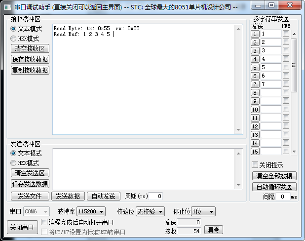
Download the program to the development board. If the detection device is ready, a single data will be written in 0x10 and multiple data will be written in 0x50.
Press KEY2 to read a byte. If it is the same as that written, it will be printed on the serial port.
Press KEY1 to read multiple bytes of data. If it is the same as the written data, the read data will be printed.