preface
as the most common display modules, LCD1602 and LCD12864 are often used for debugging. I have also encountered small projects using LCD as the display to display the measurement results of sensors. This blog briefly summarizes the use of LCD.
A small problem
How to judge whether you have an LCD with a font?
- Find the model and read the data manual
- If you don't find the data manual, you can see how many chips are behind the module. It is said that three chips (three black things) have font library, and two chips don't have font library.
- Look at the pin: it is said that if there is PSB pin, there are two CS1 and CS2 pins with font library, which are used to select the left and right half screens.
I always thought 1602 and 12864 were the same, only the difference of screen size, but later found that the use method is also different. 12864 has the function of serial data transmission, while 1602 can only use parallel data transmission.
LCD1602
Reference link
- Entry level application of LCD1602 LCD (I) - CSDN
- LCD1602 user manual, LCD1602 use details - electronic enthusiasts
- LCD1602 LCD introduction – (full version) - CSDN
Pin definition
let's take a look at the pin definition of 1602, as shown in the following figure:
when in use, connect VDD and BLA to 5V power supply, VSS and BLK to ground, and VL to a voltage signal of 0-5V. Its size will affect the actual display effect and needs to be adjusted according to the actual situation.
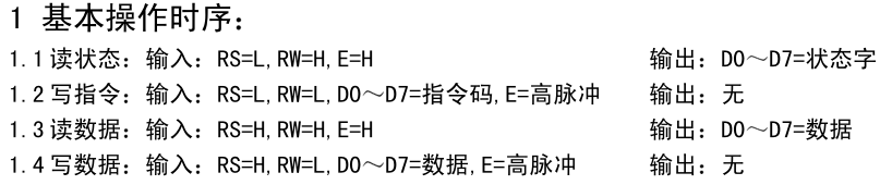
in terms of signal, RS, R/W and E are control signals, and D0~D7 are data transmission pins, which are used to input or output instructions (status) and data.
Operation sequence
Read operation sequence
Write operation timing
Timing parameters:
In summary:
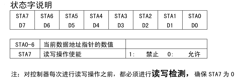
The read status word is defined as follows:
Instruction introduction
in addition to the transmission of display data, the use of LCD1602 is realized by writing different instructions. The instructions are summarized as follows:
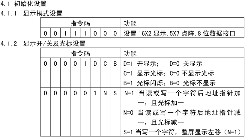
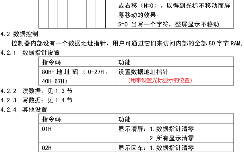
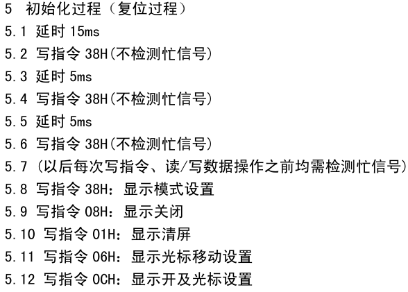
Order of initialization:
51 program example
#include<reg52. h> / / include header file

#define uint unsigned int / / predefined
#define uchar unsigned char

sbit rs=P2^6;    //1602 data / command selection control line
sbit rw=P2^5;        //1602 read / write control line
sbit en=P2^7;        //Enable control line of 1602
/*P0 D0 ~ 1602 of D7*/
uchar code table[]="1234";             //Put the contents to be displayed into the array table
void delay(uint n)       //Delay Functions
{
    uint x,y;
    for(x=n;x>0;x--)
        for(y=110;y>0;y--);
}
void lcd_wcom(uchar com)  //1602 write command function
{
    rs=0;            //Select instruction register
    rw=0;            //Select write
    P0=com;            //Send the command word to P2
    delay(5);            //After a short delay, 1602 is ready to receive data
    en=1;           //When the level of the enable line changes, the command is sent to the 8-bit data port of 1602
    en=0;
}
void lcd_wdat(uchar dat)        //1602 write data function
{
    rs=1;        //Select data register
    rw=0;        //Select write
    P0=dat;        //Send the data to be displayed to P2
    delay(5);        //After a short delay, 1602 is ready to receive data
    en=1;        //The enable line level changes, and the data is sent to the 8-bit data port of 1602
    en=0;
}
void lcd_init()              //1602 initialization function
{
    lcd_wcom(0x38);       //8-bit data, double column, 5 * 7 font
    lcd_wcom(0x0c);      //Turn on the display screen and turn off the cursor. The cursor does not flash
    lcd_wcom(0x06);    //The display address is incremented, that is, after writing a data, the display position is shifted one bit to the right
    lcd_wcom(0x01);    //Clear screen
}
void main()            //Main function
{
    uchar m=0;
    lcd_init();       //LCD initialization
    lcd_wcom(0x80);   //The display address is set to 80H (i.e. 00H), which is the first place in the upper row
    for(m=0;m<4;m++)     //Write the data in table [] to 1602 display in turn
    {
    	lcd_wdat(table[m]);
        delay(200);
    }
    while(1);        //Dynamic shutdown
}
Display Chinese characters or custom characters
according to the above method of judging whether the display module has a word library, we can find that there are only two chips in 1602, that is, there is no word library. Is there any way to display Chinese characters and custom characters? Really.
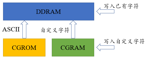
in LCD1602 module, the characters displayed in different positions are actually data from different addresses in DDRAM. The content displayed in a certain position is to write data in DDRAM of the corresponding address. Therefore, the data displayed in this way is its own data, that is, the characters in ASCII.
in addition, there are two storage locations of CGRAM and CGROM in LCD1602 module. Among them, CGROM can be regarded as the location of storing ASCII font, which can not be changed, and the power down information does not disappear. CGRAM can be read and written randomly and has 8 bytes of space to store the code of custom characters.
by carefully observing the display background of LCD1602, we can find that all the displayed contents are displayed in a 5x8 dot matrix, and the bottom line is not used, that is, 5x7 dot matrix, which is also the source of 5x7 dot matrix in LCD display instructions.
therefore, if you need to display custom characters, you need to transfer the data of setting 5x8 dot matrix to the LCD display module, as shown in the following figure is a custom ° C symbol:
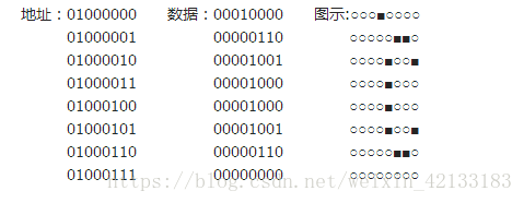
among them, each line corresponds to an 8-bit data (the upper three bits are not used and fixed to 0). A total of 8 data are required and can be placed in CGRAM. Therefore, when displaying custom characters, first write the character code in CGRAM, and then set the position where the data in CGRAM is transmitted to DDRAM. Among them, the instructions written to CGRAM are shown in the following figure:
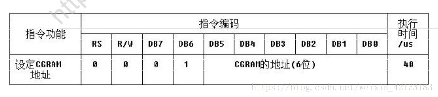
note: the above figure shows the CGRAM instruction format of 12864, while the CGRAM address of 1602 has only 8 addresses from 000 to 111 as valid addresses, and the corresponding instructions are 0x40 to 0x47.
Generally speaking, the relationship between the three is roughly as follows
The 51 procedure is as follows:
#include<reg52. h> / / include header file

#define uint unsigned int / / predefined
#define uchar unsigned char

sbit rs=P2^6;    //1602 data / command selection control line
sbit rw=P2^5;        //1602 read / write control line
sbit en=P2^7;        //Enable control line of 1602
/*P0 D0~D7 of port 1602*/
uchar code table[]={0x10,0x06,0x09,0x08,0x08,0x09,0x06,0x00};             //Put the contents to be displayed into the array table
void delay(uint n)       //Delay Functions
{
    uint x,y;
    for(x=n;x>0;x--)
        for(y=110;y>0;y--);
}
void lcd_wcom(uchar com)  //1602 write command function
{
    rs=0;            //Select instruction register
    rw=0;            //Select write
    P0=com;            //Send the command word to P2
    delay(5);            //After a short delay, 1602 is ready to receive data
    en=1;           //When the level of the enable line changes, the command is sent to the 8-bit data port of 1602
    en=0;
}
void lcd_wdat(uchar dat)        //1602 write data function
{
    rs=1;        //Select data register
    rw=0;        //Select write
    P0=dat;        //Send the data to be displayed to P2
    delay(5);        //After a short delay, 1602 is ready to receive data
    en=1;        //The enable line level changes, and the data is sent to the 8-bit data port of 1602
    en=0;
}
void lcd_init()              //1602 initialization function
{
    lcd_wcom(0x38);       //8-bit data, double column, 5 * 7 font
    lcd_wcom(0x0c);      //Turn on the display screen and turn off the cursor. The cursor does not flash
    lcd_wcom(0x06);    //The display address is incremented, that is, after writing a data, the display position is shifted one bit to the right
    lcd_wcom(0x01);    //Clear screen
}
void main()            //Main function
{
    uchar m;
    lcd_init();       //LCD initialization

    lcd_wcom(0x40);//Set the CGRAM address and store the custom characters

    for(m=0;m<8;m++)     //Write the data in table [] to 1602 display in turn
    {
	    lcd_wdat(table[m]);
	    delay(200);
    }

    lcd_wcom(0x85);   //The display address is set to 85H, which is in the middle of the upper row

    lcd_wdat(0);

    while(1);        //Dynamic shutdown
}
note: when the user-defined character is finally written, a 0 is also written. My understanding is that this step is the normal instruction to write the display content, but without inputting data from D0~D7 pins, the module will automatically call the data in CGRAM. This 0 cannot be replaced with any other data!
after testing, it is found that if you want to display two different custom characters, there is likely to be conflict and the display effect is poor.
LCD12864
Pin definition
for LCD12864, there are two working modes, serial and parallel. When PSB pin is at low level, it works in serial mode. At this time, its communication mode is similar to SPI. It communicates by three pins CS (chip selection), Sid (data input end) and CLK (clock input end), so its data transmission ports DB0~DB7 are invalid; When PSB pin is at high level, it works in parallel mode. At this time, RS (CS), R/W (SID) and E (CLK) are control signal input terminals, and DB0~DB7 are data input and output terminals.
therefore, the pins used in serial and parallel modes are also different, as shown in the following figure:
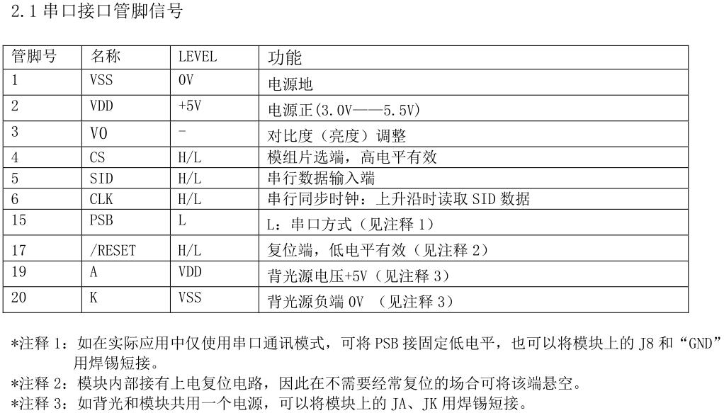
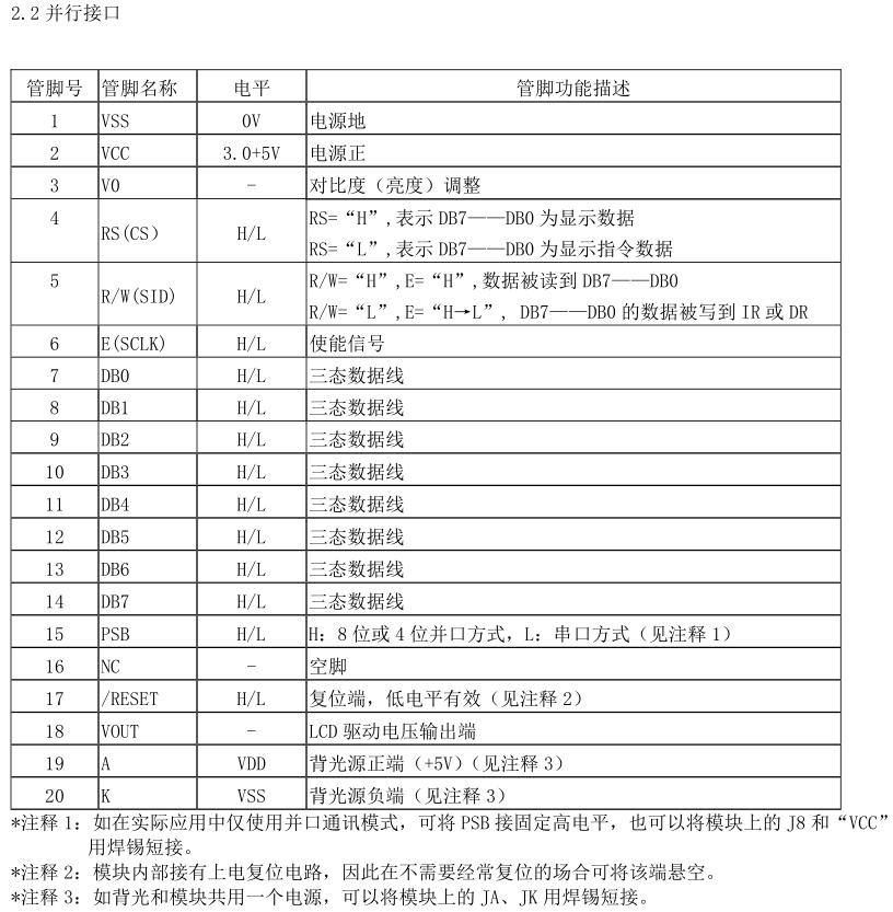
among them, since the working mode of parallel pin is very close to LCD1602, and serial operation is more popular at present, only serial control method is introduced here, and parallel control method can refer to 1602
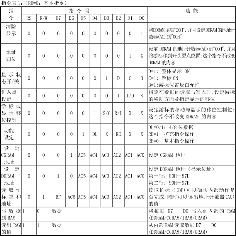
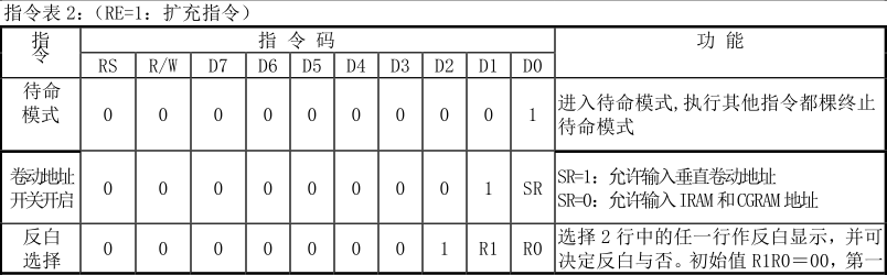
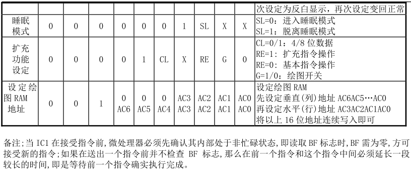
Instruction set
in LCD12864, there are two sets of instructions: basic instruction and extended instruction. Which set of instructions can be selected by inputting instructions. The specific instructions are as follows:
Initialization process
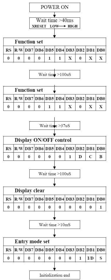
it can be set according to your own needs according to the above instruction table.
Serial operation sequence diagram
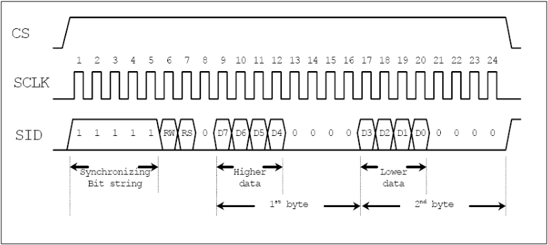
this picture needs to be looked at carefully. The first is the CS signal, which must be high level when transmitting data. If you don't need to consider so much, you can directly connect the VCC to make it always effective.
then the SCLK signal. Careful observation shows that the data should be prepared before the rising edge of SCLK generates data transmission, that is, the rising edge of SCLK.
finally, the SID signal. It can be seen from the figure that 24 clocks are required to transmit one byte of data each time, that is, 3 bytes. The first byte is to select whether to transmit data or transmission instruction, the second byte is the upper 4 bits of the data byte plus 4 zeros, and the third byte is the lower 4 bits of the data byte plus 4 zeros.
51 routine
#include "LCD.h"

void delay_us(uint8_t time)
{
	time *= 0.9;   //The crystal oscillator is 11.0592MHz
	while(time--);
}

void delay_ms(uint8_t times)
{
	while(times--)
	{
		delay_us(1000);
	}
}

void send_byte(uint8_t byte)
{
	uint8_t i;
	for(i=0; i<8; i++)
	{
		if((byte << i) & 0x80)  //Start at the top
		{
			LCD_SID = 1;
		}
		else
		{
			LCD_SID = 0;
		}
		LCD_SCK = 0;
//		delay_us(5);
		LCD_SCK = 1;
	}
}

void write_cmd(unsigned char cmdcode)
{
//	delay_ms(1);
    send_byte(0xf8);    //Tell 12864 to transfer the command next
    send_byte(cmdcode & 0xf0);     //Transmit the upper 4 bits first
    send_byte((cmdcode << 4) & 0xf0);  //Rear transmission low 4 bits
//    delay_us(100);       // Delay data writing
}

void write_data(unsigned char Dispdata)
{
//	delay_ms(1);
    send_byte(0xfa);         //Tell 12864 to transfer data next
    send_byte(Dispdata & 0xf0);   //Transmit the upper 4 bits first
    send_byte((Dispdata << 4) & 0xf0);  //Rear transmission low 4 bits
//    delay_us(100);       // Delay data writing
}

void LCD_Init(void)
{
    delay_ms(200);     //Wait for LCD self-test, with a delay of 50ms
    write_cmd(0x30);   //Basic instruction operation, 8bit
//    delay_us(150);    // Delay more than 137us
    write_cmd(0x0c);  //Display switch closed cursor
//    delay_us(110);    // Delay more than 100us
    write_cmd(0x01);  //Clear screen
    delay_ms(100);     //After the screen is cleared, wait for a period of time to achieve stability
//	write_cmd(0x06);
}

void write_str(char *s)
{
//    while(*s > 0)
//    {
//        write_data(*s);
//        s++;
//        delay_ms(5);
//    }
	unsigned char  i = 0;
    while(s[i]!='\0')
    {
        write_data(s[i]);
        i++;
        delay_ms(5);
    }
}

void write_title(void)
{
    write_cmd(0x80);    //First line
    write_str("Distance is");
    write_cmd(0x90);    //First place in the second line
    write_str("Speed is");
    write_cmd(0x88);    //First place in the third line
    write_str("Angle is");
    write_cmd(0x98);    //First in the fourth line
    write_str("Acceleration is");
    delay_ms(50);
}
there is one thing to note in the above routine: due to Keil_C51 compiler is too garbage. After testing, the pointer part of the transfer string function cannot be recognized, corresponding to the commented part of the code.
Problems and Solutions
when debugging the above part of the code, I found a very serious problem, that is, once LCD12864 displays Chinese, it always displays garbled code.
when searching for information on the Internet, I found that Keil lacked a file and needed to add it to the bin folder under the root directory, but I tried and it didn't work; There is also the need to convert the code file containing Chinese characters in Keil into ASCII encoding format. I also tried this [and I don't know what encoding format ASCII is], which doesn't work.
but the second method inspired me. I tried to change my Keil encoding format to GB2312 [originally changed to UTF-8 for better looking fonts], and then saved the file in GB2312 encoding format through Notepads. Unexpectedly, I found that the problem had been solved!
Advanced applications: display custom characters
like 1602, 12864 also has the function of displaying custom characters, and the use method is very similar. It is also the code of writing custom characters to CGRAM, and then writing them to DDRAM for display.
it is worth mentioning that the CGRAM in 12864 has four groups of 16x16 space, a total of 128 bytes, and can display four 16x16 custom Chinese characters or symbols. Its instructions are shown in the figure below:

referring to the instruction table, it can be concluded that the instruction addresses of the four Chinese characters are 0x40~0x4F, 0x50 ~ 0x5F, 0x60 ~ 0x6F and 0x70 ~ 0x7F. With the help of the modeling software, the user-defined characters can be obtained. Among them, the 16 bits of each line are divided into high 8 bits and low 8 bits, two bytes, and then the next line is opened.