1, Experimental purpose
- Familiar with the hardware connection of serial port of STM32 module;
- Master the initialization method of serial port, data sending and receiving function;
- Master interrupt initialization method and interrupt service function;
- The serial port debugging assistant on PC is used for programming, and the LEDs D7 and D8 on the control board are used;
- Proficient in KEIL project configuration, compilation, debugging and download.
2, Experimental environment
- Operating system: WINDOWS 10
- Development tools: Keil 4, UartAssists
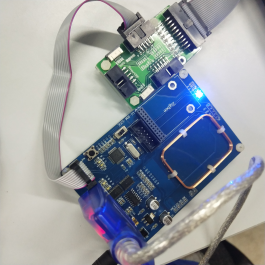
- Experimental equipment: 125K RFID reader module, JLink online debugger, power supply, USB to serial port, PC
3, Experimental content
1. Experimental tasks
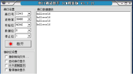
after running the program, the LED lights D7 and D8 are all off according to the, and the "hello world" is sent to the serial port circularly. Send commands' O 'and' F 'through the serial port, and the control light is on or off.
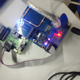
125K RFID reader module, JLink online debugger, USB to serial port, power supply and PC are used in this experiment.
2. Experimental steps
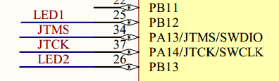
1. Check the hardware schematic diagram and find the LED D2 and D3 related to RS232 on the board and the GPIO port connected to RX and TX;
2. Open the given STM32 project template, and the project file is in the Object folder. Understand the role of main documents of the template;
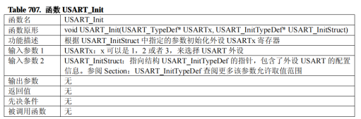
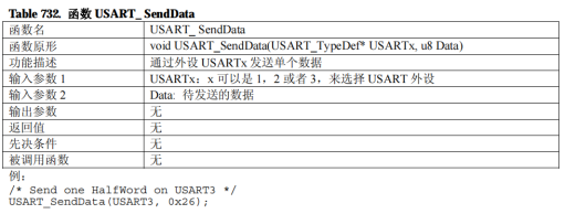
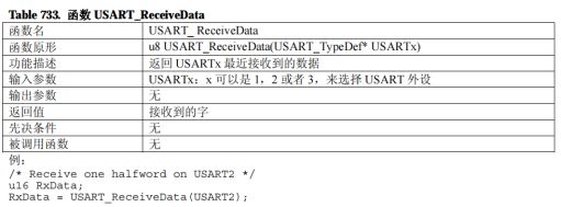
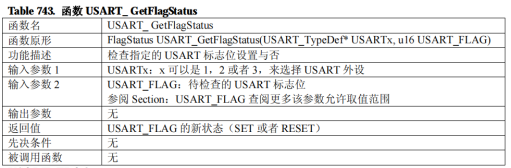
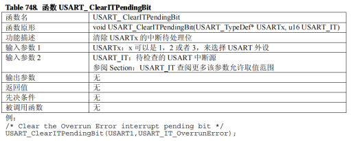
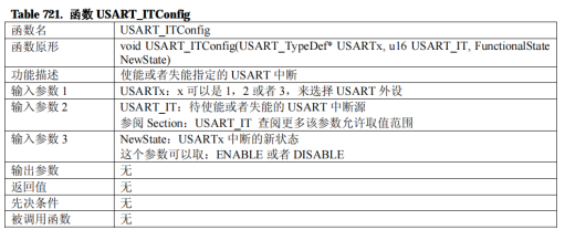
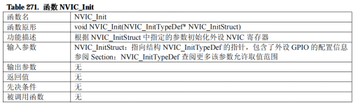
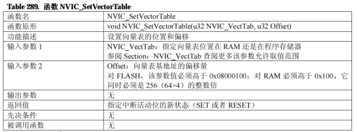
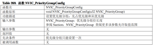
3. Understand the functions in USART firmware library and misc firmware library. Refer to the document STM32 firmware library user manual (Chinese) for key analysis; Master USART_Init(),USART_SendData(),USART_ReceiveData(),USART_GetFlagStatus(),USART_ClearITPendingBit,NVIC_Init(),NVIC_SetVectorTable(),NVIC_PriorityGroupConfig(),USART_ The function and usage of itconfig();
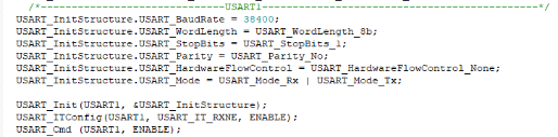
4. Check the code and the initialization function USART of USART1_ CFG (), the parameters are as follows: baud rate 38400, data bit 8, stop bit 1, no check bit, no flow control; Interrupt initialization code of USART1 to enable receiving interrupt;
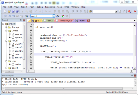
5. calling GPIO in the main function and initializing after interruption, using USART_SendData() function circularly sends "helloworld";
6. Compile, download and run, and open the serial port debugging assistant ussart on the PC Exe, after connecting, check whether it can be received;
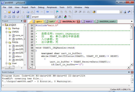
7. Open the interrupt service function usart1 of the serial port_ IRQHandler( ). Judge whether it is acceptable and accept a character. If it is judged as' O ', turn on D7 and D8 LEDs; If it is' F ', turn off two LED lights;
8. Compile and run again, send O or F from the serial port assistant respectively, and test whether the function is normal
Source code:
#include"main.h"
int main(void)
{
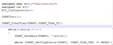
unsigned char str[]="helloworld\n";
unsigned int k=0;
RCC_Configuration();
USARTInit();
USART_ClearFlag(USART1,USART_FLAG_TC);
while(*(str+k)!='\0')
{
USART_SendData(USART1, *(str+k));
while (USART_GetFlagStatus(USART1, USART_FLAG_TXE) == RESET);
k++;
}
while(USART_GetFlagStatus(USART1,USART_FLAG_TC)==RESET);
}
#include"main.h"
/*------------------------------------------------------------------
Function name: GPIO_config
Function: GPIO initialization, configuration LED D7, D8 corresponding pin is push-pull output;
Entry parameters: None
Outlet parameters: None
-------------------------------------------------------------------*/
void GPIO_config(void)
{
GPIO_InitTypeDef GPIO_InitStructure;
RCC_APB2PeriphClockCmd(RCC_APB2Periph_GPIOB , ENABLE);
GPIO_InitStructure.GPIO_Pin = GPIO_Pin_12|GPIO_Pin_13; //SHD and mod are in there, too
GPIO_InitStructure.GPIO_Speed = GPIO_Speed_50MHz;
GPIO_InitStructure.GPIO_Mode= GPIO_Mode_Out_PP;
GPIO_Init(GPIOB, &GPIO_InitStructure);
}
/*------------------------------------------------------------------
Function name: Delay_ARMJISHU
Function: delay
Entry parameters: None
Outlet parameters: None
-------------------------------------------------------------------*/
void Delay_ARMJISHU(__IO uint32_t nCount) //Delay procedure
{
unsigned int i,k;
for(i=0;i<nCount;i++)
for(k=0;k<12000;k++);
}
#include"main.h"
/**********************************************************************************
* Function name: USART1_IRQHandler
* Function: serial port 1 receives interrupt function
* Entry parameters: None
* Outlet parameters: None
**********************************************************************************/
void USART1_IRQHandler(void)
{
unsigned char uart_in_buffer;
while(USART_GetITStatus(USART1, USART_IT_RXNE)!= RESET)
{
uart_in_buffer = USART_ReceiveData(USART1);
if(uart_in_buffer=='O')
{
GPIO_ResetBits(GPIOB,GPIO_Pin_12);
GPIO_ResetBits(GPIOB,GPIO_Pin_13);
Delay_ARMJISHU(1000);
}
if(uart_in_buffer=='F')
{
GPIO_SetBits(GPIOB,GPIO_Pin_12);
GPIO_SetBits(GPIOB,GPIO_Pin_13);
Delay_ARMJISHU(1000);
}
USART_ClearITPendingBit(USART1,USART_IT_RXNE);
}
}
summary
Serial communication is a very common serial communication mode between devices. Because it is simple and convenient, most electronic devices support this communication mode, and its communication protocol can be layered into protocol layer and physical layer. The physical layer specifies the characteristics of mechanical and electronic functions in the communication protocol, so as to ensure the transmission of original data in the physical media; The protocol layer mainly specifies the communication logic and unifies the data packaging and unpacking standards of both parties. Generally speaking, the physical layer stipulates whether we communicate with our mouth or body, and the protocol layer stipulates whether we communicate in Chinese or English. Next, analyze the physical layer and protocol layer of serial communication protocol.
USART (universal synchronous asynchronous transceiver) is a serial communication device, which can flexibly exchange full duplex data with external devices. Different from USART, there is also a UART, which cuts out the synchronous communication function on the basis of USART, and only asynchronous communication. The simple distinction between synchronous and asynchronous is to see whether the clock output needs to be provided during communication. The serial port communication we usually use is basically UART. USART can be used in STM32 to "print" program information at most. Generally, a USART communication interface is reserved to connect to the computer during hardware design, so that some debugging information can be "printed" on the serial port debugging assistant tool at the computer end in the debugging program, so as to understand whether the program is running correctly, if there is an error, where there is an error, etc.
in stm32f10x_ it. The interrupt function corresponding to USART1 interrupt source is written in C, and the function in firmware library is used
USART_ReceiveData(DEBUG_USARTx); Receiving function
USART_SendData(DEBUG_USARTx, x); Send function
USART_GetITStatus(DEBUG_USARTx, USART_IT_RXNE); Judgment flag bit function
through this experiment, be familiar with the hardware connection of the serial port of STM32 module; Understand the initialization method of serial port, data sending and receiving function; Master interrupt initialization method and interrupt service function; Master USART_Init(),USART_SendData(),USART_ReceiveData(),USART_GetFlagStatus(),USART_ClearITPendingBit,NVIC_Init(),NVIC_SetVectorTable(),NVIC_PriorityGroupConfig(),USART_ The function and usage of itconfig(); The serial port debugging assistant on PC is used for programming, and the LEDs D7 and D8 on the control board are used;