The content is extracted from the final experimental report of embedded system course design last semester. I am even the team leader (laughter). Compared with the previous experiment, the same hardware is used, so the hardware schematic diagram is exactly the same, but the functions are completely different. Because CSDN doesn't support uploading word data, I'll extract it and write it into the article. I hope it can help you
The first chapter is introduction
1.1 topic selection background
In China, in 1958, Beijing Institute of Posts and Telecommunications developed an electronic tube single tone electronic organ. For various reasons, it was not until 1977 that China produced electronic organs in large quantities. In 1989, China produced 2 million children's electronic organs per year and exported 390000. China's electronic organ industry is developing rapidly.
The electronic organ has developed rapidly, and its functions are becoming more and more perfect. Timbre and rhythm have developed from the first few to hundreds now. In addition to storing the sound color, you can also connect the sound color card through the slot. Some functions of synthesizer, such as editing and modifying timbre, self editing rhythm, multi track recording, performance program memory and so on, are also applied to electronic organ.
1.2 project demand analysis
1.2.1 basic functions
Press each key so that the buzzer will sound, and according to different keys, the buzzer will sound different tones and the corresponding led light will illuminate. When you let go, the buzzer will automatically stop sounding.
Function expansion
After pressing a specific key, the buzzer will play a specific song.
1.3 main work of the paper
The paper mainly includes four parts. The first part is the introduction, which briefly introduces the design background and functions of the subject; The second part is the overall scheme design of the system. This part mainly expounds the design idea and system design block diagram of the electronic organ, and summarizes the electronic organ as a whole; The third part is the implementation process and key technology analysis of the system. This part mainly analyzes the software and hardware involved in the electronic organ; The fourth part is the problems and solutions, which explains the problems and solutions encountered in the design process; The last part is the summary and prospect, which mainly analyzes the advantages and disadvantages of the design scheme of this subject, and gives the improvement direction in the future.
The second chapter is the overall scheme design of the system
2.1 design idea
The main design ideas of the system are: 1 Open the device file and define variables. 2. Press the keys in sequence, the buzzer will sound according to the corresponding tone, and the led lights will also light in sequence. 3. Press the special key to play the song.
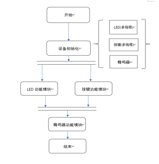
2.2 system block diagram
According to the function, the system can be divided into LED module, key module and buzzer module. The specific system block diagram is as follows:
Chapter III key technology analysis and implementation process
The key technology of the project is mainly divided into software and hardware. The hardware mainly includes three parts: LED module, key module and buzzer module. Next, I introduce these three modules respectively.
3.1 system hardware driver
3.1.1 LED module
The hardware circuit is as follows:
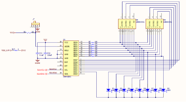
In the figure, U3 is CH452, U8 and U9 are two 3-bit nixie tubes. CH452 is a nixie tube display driver and keyboard scanning control chip. It has a built-in clock oscillation circuit, which can dynamically drive 8-bit nixie tubes or 64 LED s. It has the functions of BCD decoding, flickering, shifting, segment addressing, light column decoding and so on. At the same time, it can also scan the keyboard with 64 keys. CH452 exchanges data with the main chip through the cascadable 4-wire serial interface or 2-wire IIC serial interface. The CH452 chip of the training platform is connected with the main chip of S5PV210 by means of 2-wire interface.
Procedure:
/*********************CH452******************/
void CH452_I2c_WrByte(unsigned char dat)	//Write a byte of data
{
	unsigned char i;
	CH452_SDA_D_OUT;   /* Set SDA as output direction */
	for(i=0;i!=8;i++)  // Output 8-bit data
	{
		if(dat&0x80) {CH452_SDA_SET;}
		else {CH452_SDA_CLR;}
		DELAY_1US;//Delay 1US
		CH452_SCL_SET;
		dat<<=1;
		DELAY_1US;
		DELAY_1US;
		CH452_SCL_CLR;
		DELAY_1US;
	}
	CH452_SDA_D_IN;   /* Set SDA as input direction */
	CH452_SDA_SET;
	DELAY_1US;
	CH452_SCL_SET;  // Receive response
	DELAY_1US;
	DELAY_1US;
	CH452_SCL_CLR;
	DELAY_1US;
}
void CH452_Write(unsigned short cmd)
{
	CH452_I2c_Start();
#ifdef 	 ENABLE_2_CH452 				//  If two CH452 are connected in parallel
	CH452_I2c_WrByte(((unsigned char)(cmd>>7)&CH452_I2C_MASK)|CH452_I2C_ADDR0);  // When addr of CH452 = 0
#else
	CH452_I2c_WrByte(((unsigned char)(cmd>>7)&CH452_I2C_MASK)|CH452_I2C_ADDR1);  // When addr of CH452 = 1 (default)
#endif
	CH452_I2c_WrByte((unsigned char)cmd);
	CH452_I2c_Stop();
}
static ssize_t ch452_dev_write(struct file *file, const char *buffer,
		size_t count, loff_t *ppos)
{
	unsigned short cmd;
	int ret;
	if (count == 0) {
		return count;
	}
	ret = copy_from_user(&cmd, buffer, sizeof cmd) ? -EFAULT : 0;
//It realizes the writing from the user to the led device file
	if (ret) {
		return ret;
	}
	CH452_Write(cmd);
	return count;
}
static int ch452_open(struct inode *inode,struct file *filp)
{
   CH452_Write(CH452_RESET);
delay(100);
   CH452_Write(CH452_SYSON1);//On display
delay(100);
   CH452_Write(CH452_NO_BCD);
printk("open CH452 device");
return 0;
}
static struct file_operations CH452_fops={
        .owner=        THIS_MODULE,
        .open=         ch452_open,
        .write=		ch452_dev_write,
}; //A collection of function pointers that defines the operations that can be performed on the device. Here, there are mainly opening and writing devices.
static int __init CH452_init(void)
{
	int ret=0;
	ret = gpio_request(S5PV210_GPD1(2), "I2C1_SDA");//gpio port request
	if (ret) {
		printk("%s: request GPIO %d for 452 failed, ret = %d\n", "452",
				S5PV210_GPD1(2), ret);
		return ret;
	}
		ret = gpio_request(S5PV210_GPD1(3), "I2C1_SCL");
	if (ret) {
		printk("%s: request GPIO %d for 452 failed, ret = %d\n", "452",
				S5PV210_GPD1(3), ret);
		return ret;
	}
 ret = register_chrdev(Major, "CH452", &CH452_fops);//Registration of character devices
if(ret < 0)
        {printk("fail to registern");
return -1;
        }
        s3c_gpio_cfgpin(S5PV210_GPD1(2), S3C_GPIO_OUTPUT);//sda output
        s3c_gpio_cfgpin(S5PV210_GPD1(3), S3C_GPIO_OUTPUT);//scl output
printk("success to registern");
	return 0;
}
static void __exit CH452_exit(void)
{gpio_free(S5PV210_GPD1(2));
gpio_free(S5PV210_GPD1(3));
unregister_chrdev(Major,"CH452");
}
module_init(CH452_init);
module_exit(CH452_exit);
MODULE_LICENSE("GPL");
3.1.2 key module
The hardware circuit is as follows:
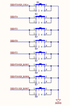
The eight keys in the circuit are connected with the S5PV210 main chip through the GPIO port. Eight ports of GPH2(4), GPH0(4), GPH0(3), GPH0(0), GPH0(2), GPH3(5), GPH3(6) and GPH3(7) are used as input terminals, and GPB7, GPB8, GPB9 and GPB10 are used as output terminals. Therefore, the corresponding port needs to be set to the corresponding input / output mode.
Procedure:
#include <linux/module.h>
#include <linux/kernel.h>
#include <linux/fs.h>
#include <linux/init.h>
#include <linux/delay.h>
#include <linux/sched.h>
#include <linux/poll.h>
#include <linux/irq.h>
#include <asm/irq.h>
#include <asm/io.h>
#include <linux/interrupt.h>
#include <asm/uaccess.h>
#include <mach/hardware.h>
#include <linux/platform_device.h>
#include <linux/cdev.h>
#include <linux/miscdevice.h>
#include <mach/map.h>
#include <mach/gpio.h>
#include <mach/regs-clock.h>
#include <mach/regs-gpio.h>
#define DEVICE_NAME "Buttons"
struct button_desc {
int gpio;
int number;
char *name;
struct timer_list timer;
};
static struct button_desc buttons[] = {
{ S5PV210_GPH2(4), 0, "KEY0" },
{ S5PV210_GPH0(4), 1, "KEY1" },
{ S5PV210_GPH0(3), 2, "KEY2" },
{ S5PV210_GPH0(0), 3, "KEY3" },
{ S5PV210_GPH0(2), 4, "KEY4" },{ S5PV210_GPH3(5), 5, "KEY5" },
{ S5PV210_GPH3(6), 6, "KEY6" },
{ S5PV210_GPH3(7), 7, "KEY7" },
};
static volatile char key_values[] = {
'0', '0', '0', '0', '0', '0', '0', '0'
};
static DECLARE_WAIT_QUEUE_HEAD(button_waitq);
static volatile int ev_press = 0;
static void lx_buttons_timer(unsigned long _data)
{
struct button_desc *bdata = (struct button_desc *)_data;
int down;
int number;
unsigned tmp;
tmp = gpio_get_value(bdata->gpio);
/* active low */
down = !tmp;
printk("KEY %d: %08x\n", bdata->number, down);
number = bdata->number;
if (down != (key_values[number] & 1)) {
key_values[number] = '0' + down;
ev_press = 1;
wake_up_interruptible(&button_waitq);
}
}
//*************Interrupt handler********
static irqreturn_t button_interrupt(int irq, void *dev_id)
{
struct button_desc *bdata = (struct button_desc *)dev_id;
mod_timer(&bdata->timer, jiffies + msecs_to_jiffies(40));//timer
return IRQ_HANDLED;
}
//************Open device **************** static int lx_buttons_open(struct inode *inode, struct file *file)
{
int irq;
int i;
int err = 0;
for (i = 0; i < ARRAY_SIZE(buttons); i++) {
if (!buttons[i].gpio)
continue;
setup_timer(&buttons[i].timer, lx_buttons_timer,
(unsigned long)&buttons[i]);
irq = gpio_to_irq(buttons[i].gpio);
err = request_irq(irq, button_interrupt, IRQ_TYPE_EDGE_BOTH,
buttons[i].name, (void *)&buttons[i]);//Register interrupts into the kernel
if (err)
break;
}
if (err) {
i--;
for (; i >= 0; i--) {
if (!buttons[i].gpio)
continue;
irq = gpio_to_irq(buttons[i].gpio);
disable_irq(irq);
free_irq(irq, (void *)&buttons[i]);
del_timer_sync(&buttons[i].timer);
}
return -EBUSY;
}
ev_press = 1;
return 0;
}
//************Turn off the device********************
static int lx_buttons_close(struct inode *inode, struct file *file)
{
int irq, i;
for (i = 0; i < ARRAY_SIZE(buttons); i++) {if (!buttons[i].gpio)
continue;
irq = gpio_to_irq(buttons[i].gpio);
free_irq(irq, (void *)&buttons[i]);//Interrupt logoff
del_timer_sync(&buttons[i].timer);
}
return 0;
}
//*************Reading device************************
static int lx_buttons_read(struct file *filp, char __user *buff,
size_t count, loff_t *offp)
{
unsigned long err;
//Blocking mode
if (!ev_press) {
if (filp->f_flags & O_NONBLOCK)
return -EAGAIN;
else
wait_event_interruptible(button_waitq, ev_press);
}
ev_press = 0;
err = copy_to_user((void *)buff, (const void *)(&key_values),
min(sizeof(key_values), count));//Read key value from device
return err ? -EFAULT : min(sizeof(key_values), count);
}
//***********Used to realize key multi-channel monitoring*************
static unsigned int lx_buttons_poll( struct file *file,
struct poll_table_struct *wait)
{
unsigned int mask = 0;
poll_wait(file, &button_waitq, wait);//Use poll_wait adds the wait queue to the
poll_table Yes.
if (ev_press)
mask |= POLLIN | POLLRDNORM;//Returns the mask that describes whether the device is readable. return mask;
}
//A collection of function pointers that defines the operations that can be performed on the device, mainly including opening, closing, reading and monitoring
 Listening device.
static struct file_operations dev_fops = {
.owner = THIS_MODULE,
.open = lx_buttons_open,
.release = lx_buttons_close,
.read = lx_buttons_read,
.poll = lx_buttons_poll,//Used to realize key multi-channel monitoring
};
//Use struct miscdevice to describe a hybrid device.
static struct miscdevice misc = {
.minor = MISC_DYNAMIC_MINOR,//Dynamically obtain the secondary equipment number and the main equipment number of hybrid equipment
 For 10
.name = DEVICE_NAME,//Device name
.fops = &dev_fops,//Set of operations for the device
};
//***************Module loading function************
static int __init button_dev_init(void)
{
int ret;
ret = misc_register(&misc);//Using misc_register function to register a hybrid device driver
 Move.
printk(DEVICE_NAME"\tinitialized\n");
return ret;
}
//***************Module unloading function*************
static void __exit button_dev_exit(void)
{
misc_deregister(&misc);//Using misc_deregister function to unregister a hybrid device driver.
}
module_init(button_dev_init);
module_exit(button_dev_exit);
MODULE_LICENSE("GPL");
MODULE_AUTHOR("Lixin Inc.");
3.1.3 buzzer module
The hardware circuit is as follows: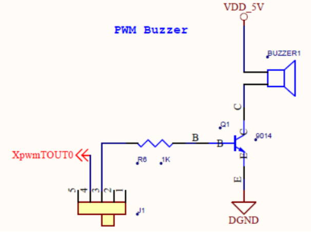
S5PV210 main chip passes GPD0 0 pin is connected to the buzzer. At high level, drive the triode Q1 to turn on and the buzzer rings. When the buzzer is driven by AC signal, the signal frequency changes the beeping frequency of the buzzer.
Procedure:
#include <linux/module.h>
#include <linux/kernel.h>
#include <linux/init.h>
#include <linux/platform_device.h>
#include <linux/fb.h>
#include <linux/backlight.h>
#include <linux/err.h>
#include <linux/pwm.h>
#include <linux/slab.h>
#include <linux/miscdevice.h>
#include <linux/delay.h>
#include <mach/gpio.h>
#include <mach/regs-gpio.h>
#include <plat/gpio-cfg.h>
#define DEVICE_NAME "pwm"
#define PWM_IOCTL_SET_FREQ 1
#define PWM_IOCTL_STOP 0
#define NS_IN_1HZ (1000000000UL)
#define BUZZER_PWM_ID 0
#define BUZZER_PMW_GPIO S5PV210_GPD0(0)
static struct pwm_device *pwm4buzzer;
static struct semaphore lock;
//**********Set the frequency of buzzer frequency conversion**********
static void pwm_set_freq(unsigned long freq) {
int period_ns = NS_IN_1HZ / freq;
pwm_config(pwm4buzzer, period_ns / 2, period_ns);
pwm_enable(pwm4buzzer);
s3c_gpio_cfgpin(BUZZER_PMW_GPIO, S3C_GPIO_SFN(2));
}
static void pwm_stop(void) {s3c_gpio_cfgpin(BUZZER_PMW_GPIO, S3C_GPIO_OUTPUT);
pwm_config(pwm4buzzer, 0, NS_IN_1HZ / 100);
pwm_disable(pwm4buzzer);
}
//************Turn on the device**************
static int mini210_pwm_open(struct inode *inode, struct file *file) {
if (!down_trylock(&lock))
return 0;
else
return -EBUSY;
}
//************Turn off the device**************
static int mini210_pwm_close(struct inode *inode, struct file *file) {
up(&lock);
return 0;
}
//***********ioctl control of equipment***************
static long mini210_pwm_ioctl(struct file *filep, unsigned int cmd,
unsigned long arg)
{
//The cmd parameter is passed in by the application
switch (cmd) {
case PWM_IOCTL_SET_FREQ:
if (arg == 0)
return -EINVAL;
pwm_set_freq(arg);
break;
case PWM_IOCTL_STOP:
default:
pwm_stop();
break;
}
return 0;
}
//A collection of function pointers that defines the operations that can be performed on the device, mainly including open, close and ioctl
 Control equipment.
static struct file_operations mini210_pwm_ops = {
.owner = THIS_MODULE,
.open = mini210_pwm_open,
.release = mini210_pwm_close, .unlocked_ioctl = mini210_pwm_ioctl,//ioctl control of equipment
};
//Use struct miscdevice to describe a hybrid device.
static struct miscdevice mini210_misc_dev = {
.minor = MISC_DYNAMIC_MINOR,//Dynamically obtain the secondary equipment number, and the primary equipment number of hybrid equipment is 10
.name = DEVICE_NAME,//Device name
.fops = &mini210_pwm_ops,//Set of operations for the device
};
//***************Module loading function************
static int __init mini210_pwm_dev_init(void) {
int ret;
ret = gpio_request(BUZZER_PMW_GPIO, DEVICE_NAME);
if (ret) {
printk("request GPIO %d for pwm failed\n", BUZZER_PMW_GPIO);
return ret;
}
gpio_set_value(BUZZER_PMW_GPIO, 0);
s3c_gpio_cfgpin(BUZZER_PMW_GPIO, S3C_GPIO_OUTPUT);
pwm4buzzer = pwm_request(BUZZER_PWM_ID, DEVICE_NAME);
if (IS_ERR(pwm4buzzer)) {
printk("request pwm %d for %s failed\n", BUZZER_PWM_ID, DEVICE_NAME);
return -ENODEV;
}
pwm_stop();
 sema_init(&lock, 1);
ret = misc_register(&mini210_misc_dev);//Using misc_deregister function to log off
 A hybrid device driver.
printk(DEVICE_NAME "\tinitialized\n");
return ret;
}
//***************Module unloading function*************
static void __exit mini210_pwm_dev_exit(void) {
pwm_stop();
misc_deregister(&mini210_misc_dev);
gpio_free(BUZZER_PMW_GPIO);
}
module_init(mini210_pwm_dev_init);
module_exit(mini210_pwm_dev_exit);MODULE_LICENSE("GPL");
MODULE_AUTHOR("FriendlyARM Inc.");
MODULE_DESCRIPTION("S5PV210 PWM Driver");
3.2 program design analysis
The code of electronic organ is as follows:
#include <stdio.h>
#include <stdlib.h>
#include <unistd.h>
#include <sys/ioctl.h>
#include <sys/types.h>
#include <sys/stat.h>
#include <fcntl.h>
#include <sys/select.h>
#include <sys/time.h>
#include <errno.h>
#include <termios.h>
#include <string.h>

#define CH452_CLR_BIT 0x0180
#define CH452_SET_BIT 0x01C0

#define PWM_IOCTL_SET_FREQ 1
#define PWM_IOCTL_STOP 0
#define ESC_KEY 0x1b

#define a1 1047
#define a2 1175
#define a3 1319
#define a4 1397
#define a5 1568
#define a6 1760
#define a7 1967

static int fd = -1;
static int led_fd = -1;
static int buttons_fd;

static void close_buzzer(void);

static void open_buzzer(void)
{
fd = open("/dev/pwm", 0);//Turn on the buzzer device
if (fd < 0)
{
perror("open pwm_buzzer device");
exit(1);
}
atexit(close_buzzer);
}

static void sleep_ms(unsigned int secs)
{
struct timeval tval;
tval.tv_sec=secs/1000;
tval.tv_usec=(secs*1000)%1000000;
select(0,NULL,NULL,NULL,&tval);
}

static void close_buzzer(void)
{
if (fd >= 0)
{
ioctl(fd, PWM_IOCTL_STOP);//Use ioctl to control the buzzer. Here is to turn off the buzzer
if (ioctl(fd, 2) < 0)
{
perror("ioctl 2:");
}
close(fd);
fd = -1;
}
}

static void stop_buzzer(void)
{
int ret = ioctl(fd, PWM_IOCTL_STOP);
if(ret < 0)
{
perror("stop the buzzer");
exit(1);
}
if (ioctl(fd, 2) < 0)
{
perror("ioctl 2:");
}
}

static void set_buzzer_freq(int freq)
{
int ret = ioctl(fd, PWM_IOCTL_SET_FREQ, freq);
if(ret < 0)
{
        perror("set the frequency of the buzzer");
        exit(1);
}
}

static open_device(void)
{
buttons_fd = open("/dev/Buttons", 0);
if (buttons_fd < 0)
    {
perror("open device buttons");
exit(1);
   }


led_fd = open("/dev/CH452", O_RDWR);
if(led_fd < 0)
        {
fprintf(stderr, "Error open: %s\n", strerror(errno));
return -1;
        }
}

int main()
{
unsigned yuepu[]={a1,a2,a3,a1,a2,a5,a5,a3,a6,a6,a6,a6,a5,a3,a5,a3,a1,a1,a1,a6,a6,a5,a3,a5,a2,a2,a3,a3,a2,a1,a3,a2};
int k = 0;

unsigned short cmd;
int r;
char buttons[8] = {'0', '0', '0', '0', '0', '0', '0', '0'};
open_device();

open_buzzer();

while(1){
char current_buttons[8];
int count_of_changed_key;
int i, j;

for (j=0;j<8;j++) //Lights out
 {
 cmd=CH452_CLR_BIT|0x08+j;
 write(led_fd,&cmd,sizeof(cmd));
 }
if(read(buttons_fd,current_buttons,sizeofcurrent_buttons)!=sizeofcurrent_buttons)
{
perror("read buttons:");
exit(1);
}

for (i = 0, count_of_changed_key = 0; i < sizeof buttons / sizeof buttons[0]; i++) //Read key
{
if (buttons[i] != current_buttons[i])
 {
 buttons[i] = current_buttons[i];
if(buttons[i] != '0')
{
 switch(i)
 {
  case 0 : {set_buzzer_freq(a1);sleep_ms(200);stop_buzzer();break;}
  case 1 : {set_buzzer_freq(a2);sleep_ms(200);stop_buzzer();break;}
  case 2 : {set_buzzer_freq(a3);sleep_ms(200);stop_buzzer();break;}
  case 3 : {set_buzzer_freq(a4);sleep_ms(200);stop_buzzer();break;}
  case 4 : {set_buzzer_freq(a5);sleep_ms(200);stop_buzzer();break;}
  case 5 : {set_buzzer_freq(a6);sleep_ms(200);stop_buzzer();break;}
  case 6 : {set_buzzer_freq(a7);sleep_ms(200);stop_buzzer();break;}
  case 7 : {
              for(k = 0; yuepu[k]>0 ; k++)
             {
              set_buzzer_freq(yuepu[k]);
              sleep_ms(1000);
              }
stop_buzzer();break;
           }
       default : break;
}
cmd=CH452_SET_BIT|0x08+i;
    write(led_fd,&cmd,sizeof(cmd));
    sleep(1);
}
printf("%skey %d is %s", count_of_changed_key? ", ": "", i+1, buttons[i] == '0' ? "up" : "down");
count_of_changed_key++;
}
}
if (count_of_changed_key)
       {
printf("\n");
}
}
close(led_fd);
close(buttons_fd);
return 0;
}
Overall analysis: in real life, when we press the key of the electronic organ, the electronic organ will sound with different tones. We assign values to seven different keys to correspond to different tones. In this way, when they are pressed, different values are output. The buzzer recognizes different values and outputs the corresponding tones. In order to realize this function, we call the function to match the key and the corresponding buzzer tone, and can output normally when pressing the key. In addition, we also assign a value to the play key, input the tone corresponding to each note of the song selection according to the appropriate frequency, and when we press the key, it will play according to the set tone, so as to achieve the function of playing the song
Chapter IV and problem solving
Problem 1: only one while loop is used in the main function. Each key is pressed to obtain the key value and overwrite the current open_ The frequency value in buzzer is not concise and robust enough.
Solution: set a switch branch in the while function, and enter a branch after entering the key value, so as to make the program concise and robust.
Problem 2: at the beginning of running the program, it is found that the buzzer will not sound according to the specified tone.
Solution: in the code, we did not set the appropriate frequency, resulting in little difference between the tone up and down and no obvious difference in hearing. Then we changed the frequency and solved it.
Question 3: after pressing the key, the buzzer can change the audio, but it keeps ringing. If it can't be asked, it only rings once
Solution: set the delay function and sleep_ms value, open_buzzer and stop_ The buzzer controls the buzzer switch. Solved.
Chapter V summary and Prospect
5.1 summary
This course design has basically completed the functions we want to achieve. Due to the problem of time, we have not solved the problem of changing the scale, which will make the pitch of the song inaccurate, which can only achieve the effect of identifying the song and can not play more perfectly, but in general, the function has been quite perfect. Through this course design, we have a certain understanding of the driver and multithreading of the main modules, and are familiar with how to complete the functions of the code through the driver.
5.2 outlook
In this course design, we set relatively accurate tones, so that the audience can have a better auditory experience when playing. Today is the Internet age. We should keep up with the trend of the times. We should keep pace with the times in designing the code of electronic organ. In the future, we can realize the replacement of multiple scales. You can also connect and call multiple buzzers to set chord background music to enrich the performance content. There are still many places we can consider, but we need to further practice and improve.
The production of electronic organ is a small experience of our software and hardware development. I hope we can make more meaningful things in the future, which can be applied to our life, enrich our life and contribute to our motherland.