This is an article before CSDN, but I can't see the picture, so I moved it.
Original address: https://blog.csdn.net/icqw1983/article/details/82702837?ops_request_misc=%257B%2522request%255Fid%2522%253A%2522161931369116780265472991%2522%252C%2522scm%2522%253A%252220140713.130102334 …%2522%257D&request_ id=161931369116780265472991&biz_ id=0&utm_ medium=distribute. pc_ search_ result. none-task-blog-2blogsobaiduend~default-3-82702837. nonecase&utm_ term=%E5%B3%B0%E5%80%BC%E6%A3%80%E6%B5%8B%E7%94%B5%E8%B7%AF
1, Foreword
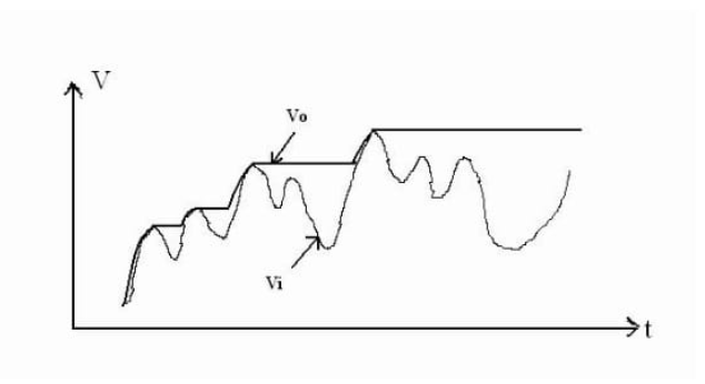
The function of Peak Detector (PKD) is to extract the peak of input signal and generate output Vo = Vpeak. In order to achieve this goal, the output value of the circuit will be maintained until a new and larger peak appears or the circuit is reset.
Peak detection circuit is widely used in AGC (automatic gain control) circuit and sensor maximum value calculation circuit. It is usually used as the judgment basis for the multiple selection of program-controlled gain amplifier. Some students like to use RMS chips such as AD637 as the criterion of programmable gain amplifier, mainly because of the convenience of integration, but personally think it is unreasonable, because the RMS is not necessarily related to the positive and negative peak of the signal; Secondly, such chips are too expensive in practical applications. Of course, electronic design competition is possible, because the test signal is always sine wave, square wave and so on. (I participated in the blog competition of TI company. If I think it's OK, I hope you can help me and reply. Thank you. I'll work harder: -)
2, Principle of peak detection circuit
As the name suggests, peak detector( PKD,Peak Detector)(This paper takes positive peak detection as an example by default) is to collect and maintain the peak value of the signal. The effects are as follows:( MS Drawing tool:
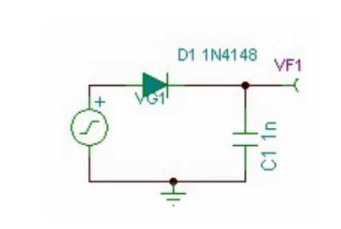
According to such requirements, we can use a diode and capacitor to form the simplest peak detector. As shown below( TINA TI 7.0 Draw:
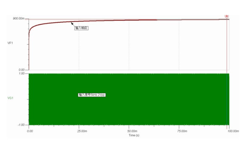
At this time, we can choose to build a circuit with bread board and connect the signal source oscilloscope to observe the results, but before that, simple verification with simulation software TINA TI will save a lot of time. Through simple simulation (input sinusoidal signal 5kHz,2Vpp), we found that the peak detector composed of only one diode and capacitor can work, but the performance is not very ideal. For 1nF capacitor, it reaches a stable peak after 100ms, with an error of 10%. Moreover, due to the lack of input and output buffer, in practical application, the charge in the capacitor will be consumed by other circuit loads, resulting in the peak detector unable to maintain the signal peak voltage.
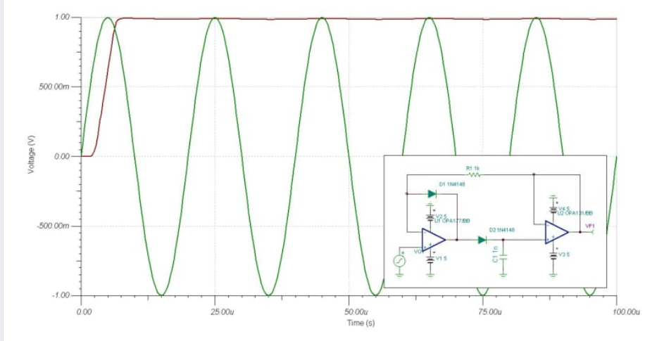
Since we want to improve, we must first analyze the deficiencies. The error detected in the above figure mainly comes from the forward conduction voltage drop with the diode, so we can replace the simple diode with the "super diode" mentioned in the analog book( TINA TI 7.0 Draw:
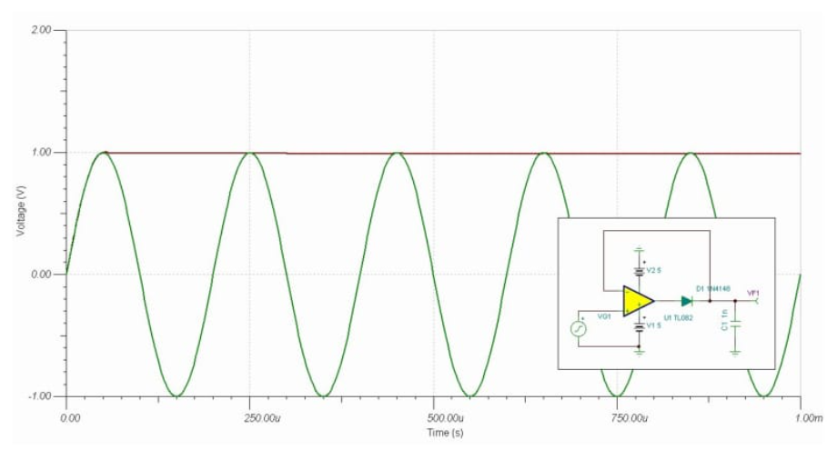
   From the simulation results, the detection error is greatly reduced under the same test conditions. But we know that one disadvantage of super diodes is Vi In the process of changing from negative voltage to positive voltage, in order to close the negative feedback loop with diodes, the op amp should end the negative saturation state, and the output voltage should be from the negative saturation voltage value to the negative saturation voltage value( Vi+V Diode). This process takes time. If the input changes in this process, the output will be distorted.

   Therefore, we need to add measures to prevent negative saturation in the circuit, that is, the processing link of our input part should be able to follow the voltage of the input signal as much as possible, provide an ideal diode as much as possible, and provide effective input buffer at the same time. A classic circuit is by adding a diode between the input and output, which is similar to voltage clamping( TINA TI 7.0 Draw:
After the above simple description, in fact, we can divide the peak detector into several modules: (1) analog peak memory, that is, capacitor; (2) Unidirectional current switch, i.e. diode; (3) Input and output buffer isolation, i.e. operational amplifier; (4) Capacitor discharge reset switch (this part is not necessary, for example, if the capacitance value is selected properly, the time interval between two sampling is large).
3, Several peak detection circuits
The peak detection circuit composed of diode and capacitor has many implementation modes and circuit forms TI We can find a lot in the company's literature. In terms of the peak value of the diode and the effective working range of the detector, it is within the range of 500 kHz Wait a minute, right m
The detection error of input signal above Vpp can reach less than 3%. The curve in 3.2 below can reflect the performance of this kind of peak detector.
3.1 discrete diode capacitance type
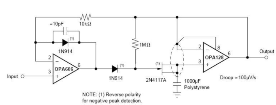
TI Corporate Difet Electrometer level operational amplifier OPA128 of DATASHEET A useful peak detector is provided in:
TINA TI The simulation results are as follows:
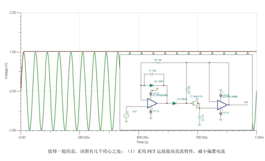
It is worth mentioning that the figure has several intentions: (1) adopt FET The operational amplifier improves the DC characteristics and reduces the bias current OPA128 The bias current is as low as 75 fA!;(2)Using FET as a diode can effectively reduce the reverse current and increase the output driving force of the first operational amplifier; (3) Small capacitors should prevent self excitation. It can be used in practical application TL082 Dual OP AMP and 1 N4148 Instead of FET, the performance and price are relatively high. See details for details http://blog.ednchina.com/billyevans/193257/message.aspx.
3.2 diode free type
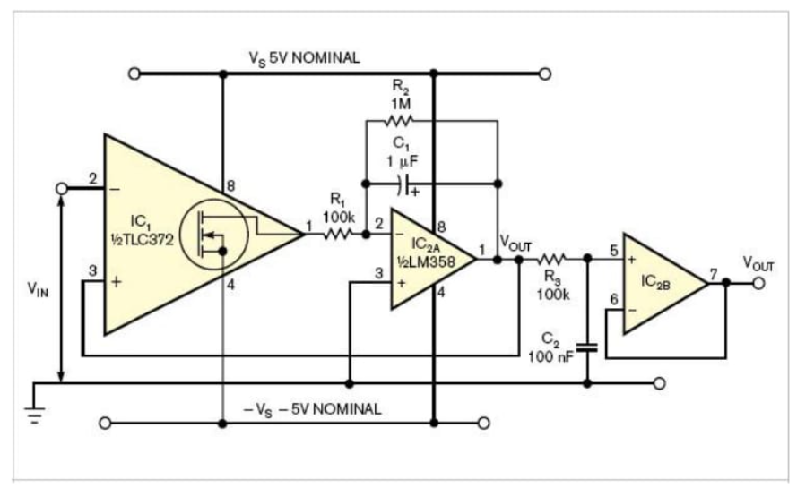
The diode free type is an open set using the output of the comparator BJT Or open the leak MOSFET Replace the diode to further improve the cost performance, TI Corporate LM311 of DATASHEET A very simple peak detector circuit is provided:
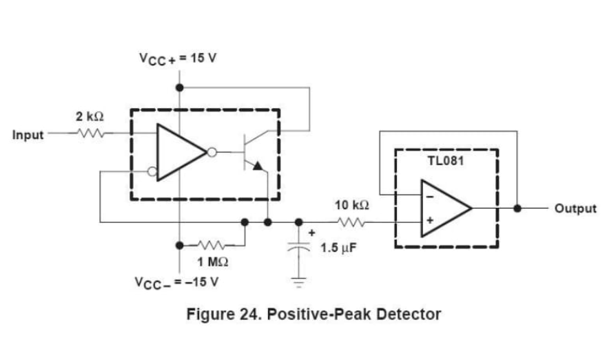
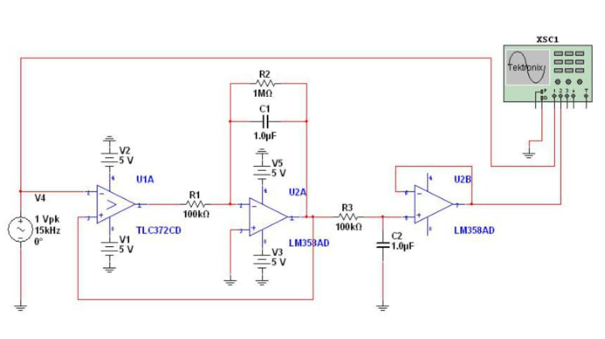
   The figure is used by the author TINA TI 7.0 and Multisim10.1 The simulation is not successful, but the circuit should have no problem, but the performance depends on the experiment.

   The point is EDN There is an article in the English Version (see references) that provides a very good way PKD:
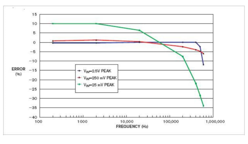
The performance is as follows:
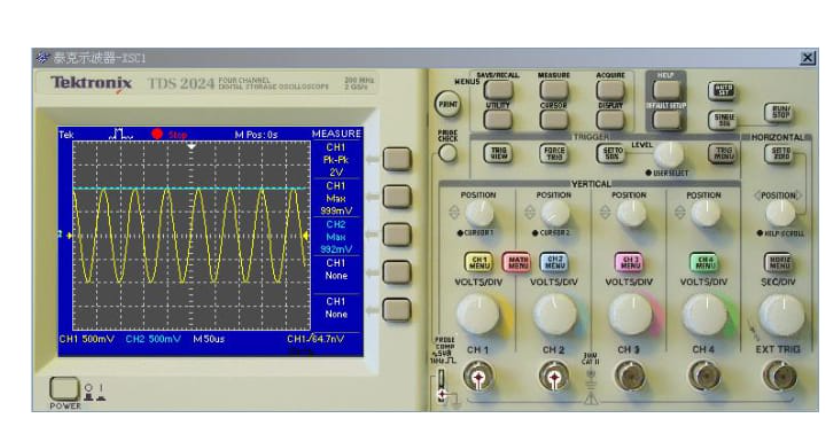
The author of this figure failed to simulate successfully with TINA, mutisim10 1. Successful simulation:
The performance is as follows:
3.3 integrated peak detection circuit
ADI The company has an integrated PKD-PKD01,The essence is the structure of diode plus capacitor, and the performance is unknown.
4, Peak detection circuit of other structures
In the high-speed environment, the circuit with diode and capacitor structure can not adapt to it. The author has seen it before FPGA+DAC+The principle of peak detector composed of high-speed comparator is very simple DAC Compare the output and input signals, FPGA be responsible for DAC Voltage output control and comparator output detection.
5, References
[1] Qu Anlian. Applied electronic technology. Science and Technology Press, 2006
[2] Hua Chengying, Tong Shibai. Fundamentals of Analog Electronic Technology (Fourth Edition). Beijing: Higher Education Press, 2006
[3] Learning resources on the official website of Texas Instruments (China)
[4] Inexpensive peak detector requires few components.Anthony H Smith
[5] Design with Operational Amplifiers and Analog Integrated Circuits.Franco, Sergio