in the last article, we mentioned Hardware construction of Nb IOT intelligent door magnet Next, let's talk about how to quickly realize the function code of NB gate magnetism through graffiti MCU SDK.
graffiti NM1 module generally burns graffiti general firmware. Just send various serial port instructions to the module according to the graffiti MCU docking serial port protocol to realize the reporting and distribution of cloud and data on the network of the device, and MCU SDK can help us focus on application development without paying too much attention to the data sending and receiving process between MCU and module
1. Create products
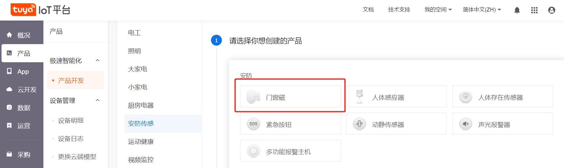
- get into Graffiti intelligent IoT platform , click create product. Select security sensing - > door and window magnetism
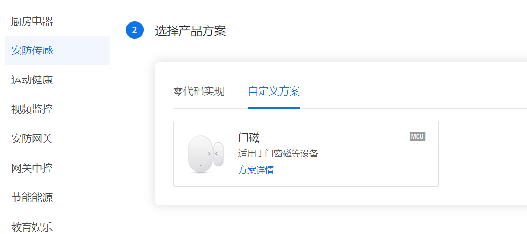
- Choose Custom scheme, choose door magnet, give a name to your product, choose NB IOT as networking mode, PSM as power consumption type, and click create product.
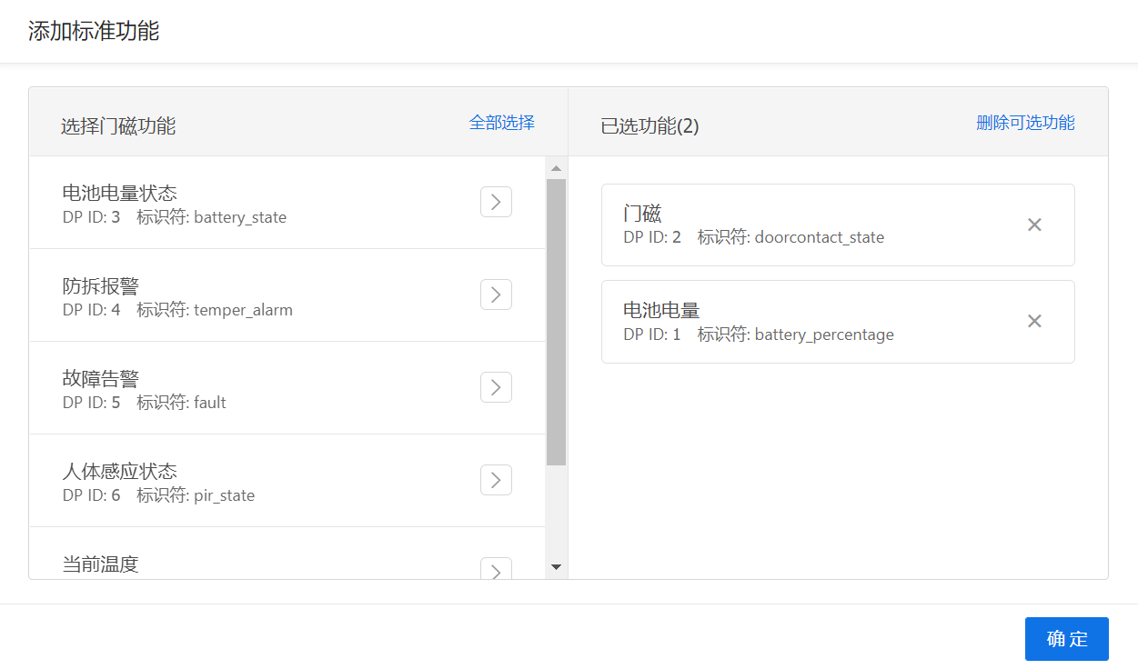
- Function selection door magnet and battery power.
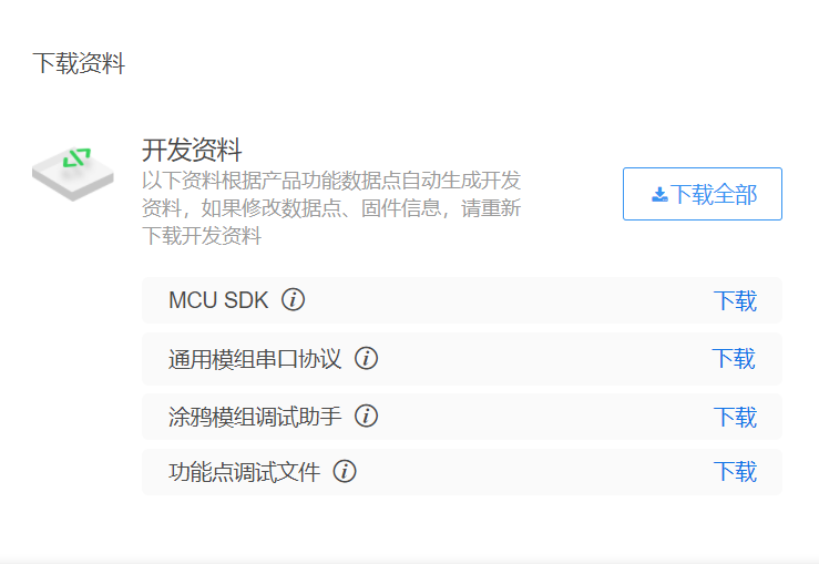
- After selecting the APP panel, click Next: hardware development. Then pull the page to the bottom and click the download all button to download the development materials for later use.
2. Module debugging
install the graffiti module debugging assistant. After opening it, import the function point debugging file (i.e. the. json file in the downloaded development data) in the setting bar of the main interface, set the baud rate to 9600, select the power consumption mode to psm and the connection mode to isp, then connect the NM1 module with the serial port tool, and click to start debugging:
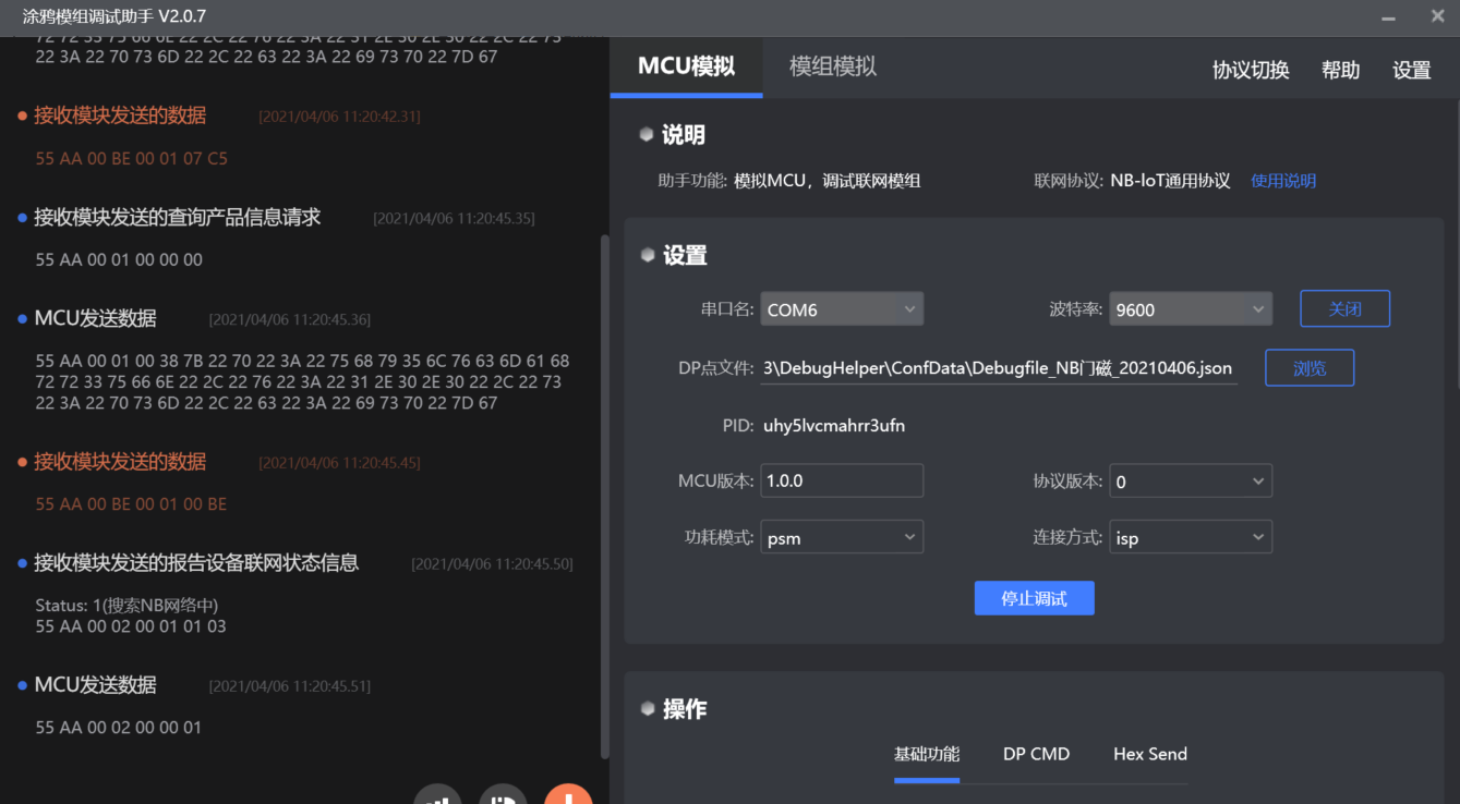
contrast NB IOT serial port protocol Observe the communication serial port data between the module on the left side of the interface and the analog MCU. If you see that the module sends the data reporting the networking status 3 (55 AA 00 02 00 01 03 XX), it means that the module is normal and successfully connected to the operator platform, but the device has not been bound and connected to the graffiti cloud.
3. Transplant MCU SDK
Refer to the document for the initial engineering code of MCU produced by STM32CubeMX MCU_SDK migration Start transplanting graffiti MCU SDK.
the MCU downloaded earlier_ After the files in SDK are added to the project, they are compiled directly, and then modified according to the error prompt:
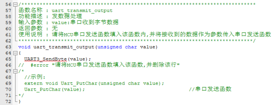
- uart_ transmit_ The output() function can be processed according to the prompt information in #error and commented out after processing.
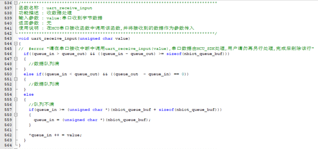
- Perfect UART_ receive_ The input () function can be processed according to the prompt information in #error and commented out after processing.
- nbiot_ uart_ The service() function can be processed according to the prompt information in #error, and then commented out.
- nbiot_ protocol_ The init() function can be processed according to the prompt information in #error and commented out after processing.
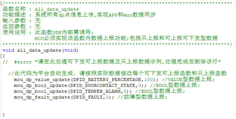
- Next is all_data_update() function, which will automatically report the information of all dp points in the system. Individuals do not need to call it.
4. Function realization
- Create a new user_func.h file, in which a structure is defined to record various states of door magnetic equipment.
// Sensor report flag
typedef enum{
    STATE_IDLE         = 0,
    STATE_DOOR_NEED_UP,
    STATE_POWER_UP,
    STATE_UP_FINISH,
}sensor_state_t;

// Door switch status
typedef enum{
	STATE_CLOSE         = 0,
	STATE_OPEN          = 1
}door_state_t;

typedef struct{
    door_state_t door_state;
	sensor_state_t sensor_state;
	unsigned char door_up_lock;      // Door status reporting lock
	unsigned char remaining_power;   // Remaining power of equipment, unit percentage
}device_status_t;
- In the new user_func.c file to achieve some custom functions, at the same time in nbiot H file, add the header file #include "user_func.h".
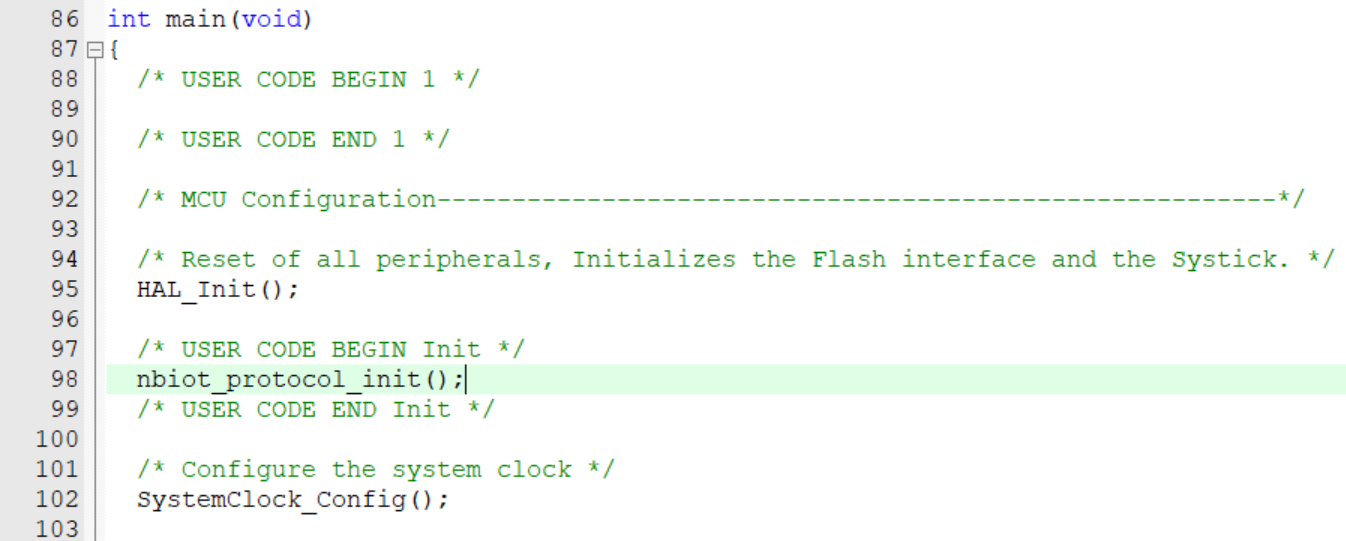
- In main C in the document:
Add header file #include "nbiot.h"
After the MCU is powered on and started and before entering the while(1) {} cycle, in addition to the conventional configuration of IO port, serial port and ADC, the following shall be executed:
nbiot_protocol_init();

//Enable low power mode clock
__HAL_RCC_PWR_CLK_ENABLE();

//Initialize the level of wake-up pin of NB module
HAL_GPIO_WritePin(GPIOB,GPIO_PIN_5,GPIO_PIN_SET);
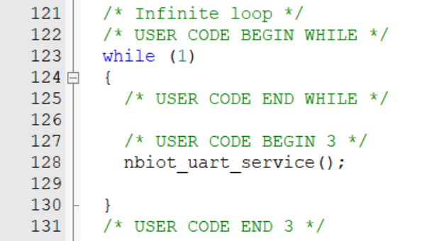
In the while(1) {} loop:
while (1)
{
    nbiot_uart_service();

    power_detect_poll();

    user_sensor_up_poll();
}
nbiot_uart_service() is a serial port data processing function provided by SDK, which parses and processes the data returned by NB IOT module.
power_detect_poll() is the battery power detection function, in which the approximate remaining power is obtained and saved through ADC sampling and conversion. By developers themselves.
- user_sensor_up_poll() is the sensor report task processing function. It judges whether to send the report data and whether to let the MCU enter the STOP low-power mode according to the equipment status of NB module and other factors. By developers themselves.
void user_sensor_up_poll(void)
{
    if(device_status_s.door_up_lock) {
		// Interpret the door status reporting task that has not been processed, and start sending the reporting data to the NB module.
        if(STATE_DOOR_NEED_UP == device_status_s.sensor_state) {
            mcu_dp_bool_update(DPID_DOORCONTACT_STATE, device_status_s.door_state);
            device_status_s.door_up_lock = 0;
        } else if(STATE_POWER_UP == device_status_s.sensor_state) {
            mcu_dp_value_update(DPID_BATTERY_PERCENTAGE, device_status_s.remaining_power);
					  device_status_s.door_up_lock = 0;
        }else if(STATE_UP_FINISH == device_status_s.sensor_state) {
					  device_status_s.sensor_state = STATE_IDLE;
				    device_status_s.door_up_lock = 0;

			    // Open the PSM sleep lock of NB module
            //mcu_set_nbiot_sleeplock(0);
			    // MCU enters low power consumption mode
            enter_lowpower_mode();
        }
    }
}
- Realize two functions of entering and exiting low-power mode:
void enter_lowpower_mode()
{
    HAL_GPIO_WritePin(GPIOB,GPIO_PIN_5,GPIO_PIN_SET);

    lowpower_gpio_init();

    HAL_ADC_Stop(&hadc1);
    HAL_ADC_DeInit(&hadc1);

    HAL_UART_DeInit(&huart3);

    // HAL_TIM_Base_DeInit(&htim3);

    // Turn off the clock
    __HAL_RCC_DMA1_CLK_DISABLE();
    __HAL_RCC_GPIOB_CLK_DISABLE();
    __HAL_RCC_GPIOC_CLK_DISABLE();
    __HAL_RCC_GPIOC_CLK_DISABLE();
    __HAL_RCC_GPIOD_CLK_DISABLE();
    __HAL_RCC_GPIOF_CLK_DISABLE();

    HAL_SuspendTick();
    // Enter stop mode
    HAL_PWR_EnterSTOPMode(PWR_MAINREGULATOR_ON,PWR_STOPENTRY_WFI);
}

void leave_lowpower_mode()
{
    SystemClock_Config();

    MX_GPIO_Init();

    // MX_TIM3_Init();

    MX_USART3_UART_Init();
    __HAL_UART_ENABLE_IT(&huart3, UART_IT_RXNE);

    MX_ADC1_Init();
    HAL_ADC_Start(&hadc1);

    // Pull up the pin to wake up the NB module
    HAL_GPIO_WritePin(GPIOB,GPIO_PIN_5,GPIO_PIN_RESET);
	delay_ms(200);
	HAL_GPIO_WritePin(GPIOB,GPIO_PIN_5,GPIO_PIN_SET);

    // The sensor needs to report the door switch status
    device_status_s.sensor_state = STATE_DOOR_NEED_UP;
}
- The stop low power mode of MCU is mainly aroused by interrupt, so it is necessary to call nbiot_ in the interrupt callback function. uart_ Service() and record the opening and closing status of the door:
void HAL_GPIO_EXTI_Falling_Callback(uint16_t GPIO_Pin)
{
	leave_lowpower_mode();
	device_status_s.door_state = STATE_OPEN;
}


void HAL_GPIO_EXTI_Rising_Callback(uint16_t GPIO_Pin)
{
	leave_lowpower_mode();
	device_status_s.door_state = STATE_CLOSE;
}
- Since the NB module wakes up from the PSM mode and needs to reconnect to the graffiti cloud, the mcu needs to wait until the module is successfully connected before reporting dp data. In system Data under C file_ The working state of the handle function is recoded, and the code implementation is added to the processing case:
case NBIOT_STATE_CMD: //working condition
nbiot_work_state = nbiot_uart_rx_buf[offset + DATA_START];
nbiot_uart_write_frame(NBIOT_STATE_CMD,0);
if (NB_STATE_DEVICE_BINDED == mcu_get_nbiot_work_state()) {
//When the module is connected to the graffiti cloud, open the door magnetic reporting lock to allow dp reporting
device_status_s.door_up_lock = 1;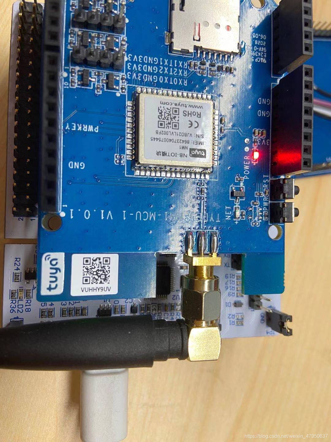
}else {
device_status_s.door_up_lock = 0;
}
break;
- In system Data under C file_ Add code to the report back code processing case of handle function:
case STATE_UPLOAD_CMD:
	// Judge the value of result, after confirming the receipt of the information returned by the module, open the door status report lock and prepare for the next report
    device_status_s.door_up_lock = 1;
    device_status_s.sensor_state++;
break;
5. Device binding
- After the compilation and burning of MCU firmware, the device can be bound.
- Open the graffiti smart APP, click the + sign in the upper right corner, and start scanning QR code
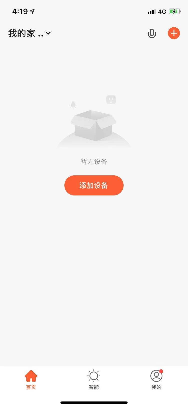
- Scan the QR code on the NM1 module board and bind the equipment

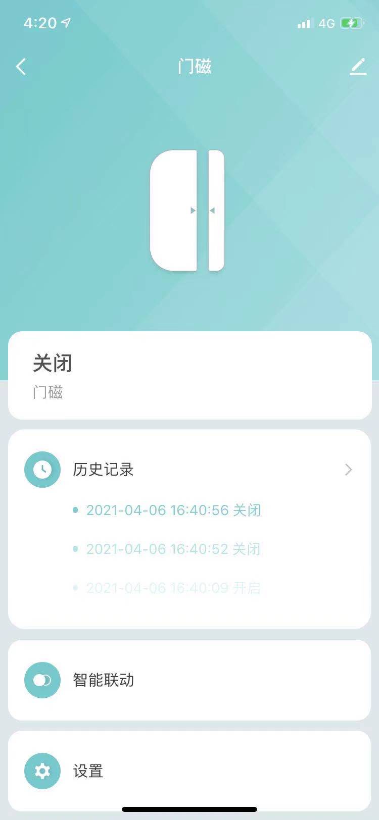
- After the binding is successful, the device can upload the door magnetic switch status to the APP