preface
In this paper, I take STM32G0B1 as the platform to record the debugging summary for reference only. If there is anything wrong, please correct it.
1, Experimental environment?
1)MCU: STM32FG0B1VCT6 2) Can tool: Guangcheng CAN Bus Analyzer dual channel can to usb module USBCAN debugging and analysis tool can card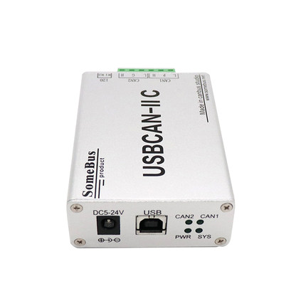
3) CAN transceiver: TCAN1042DRQ1
4) STM32CubeMX version: V6 three
5) Firmware version: stm32cube FW_ G0 V1. five
6) Emulator: ST-LINK V2
7)MDK: V5.30.0.0
2, Difference between CAN and FDCAN
1. Introduction
CAN: in 1986, Bosch, a German electrical supplier, developed a CAN communication protocol for automobiles
CAN_FD: with the increase of people's requirements for data transmission bandwidth, the traditional CAN bus is difficult to meet this increased demand due to the limitation of bandwidth. In addition, in order to narrow the bandwidth gap between can network (max. 1MBit/s) and FlexRay(max.10MBit/s), BOSCH launched CAN FD in 2011.
2. What are the advantages of fdcan (personal perspective):
1) The speed is faster, up to 10M, and 5M is widely used.
2) The maximum length of a packet of data is 64 bytes, while the maximum length of a packet of ordinary CAN is 8 bytes, which greatly improves the communication efficiency.
3)CAN_ The full name of FD is flexible data rate, which means that the baud rate of the data segment in the frame message is variable, that is, the arbitration segment and data control segment use the standard communication baud rate, and will switch to a higher communication baud rate when transmitting the data segment.
3, CAN send
1. Screenshot of stm32cubemx configuration:
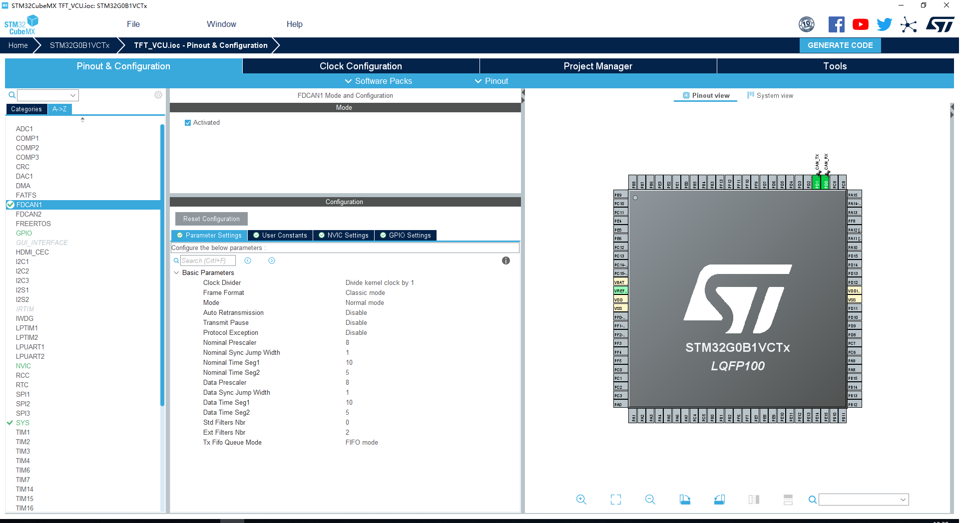
1) Clock Divider: indicates that the CAN clock is frequency divided. The STM32G0B1 clock supports 64M at most. Select no frequency division here.
2) Frame Format: select the classic mode here, that is, take it as the ordinary CAN mode.
3) Mode: normal working mode is selected here, and loop back mode is also selected.
4) Nominal Prescaler: indicates the frequency division coefficient of arbitration section and data control section
5) Nominal Sync Jump Width: resynchronizes the jump width.
6) Nominal Time Seg1 and Nominal Time Seg2: related to setting baud rate, BAUD=Freq/Clock Divider/Prescaler/(Seg1+Seg2+1)=64M/1/8/(10+5+1)=500K
7) The following Data is similar to the above.
8) Std Filters Nbr: number of standard frame filters. It refers to the number of filters used when configuring CAN acceptance. Write as many as you use.
9) Ext Filters Nbr: number of extended frame filters.
2. Contents to be added by users:
1) Add the following during initialization:
 if (HAL_FDCAN_Start(&hfdcan2) != HAL_OK)
  {
   Error_Handler();
  }
2) Add the following to the main loop:
    TxHeader.Identifier = 0x0fffffff;
    TxHeader.IdType = FDCAN_EXTENDED_ID;
    TxHeader.TxFrameType = FDCAN_DATA_FRAME;
    TxHeader.DataLength = FDCAN_DLC_BYTES_8;
    TxHeader.ErrorStateIndicator = FDCAN_ESI_ACTIVE;
    TxHeader.BitRateSwitch = FDCAN_BRS_OFF;
    TxHeader.FDFormat = FDCAN_CLASSIC_CAN;
    TxHeader.TxEventFifoControl = FDCAN_NO_TX_EVENTS;
    TxHeader.MessageMarker = 0;

    ++TxData[7];

    if(HAL_FDCAN_AddMessageToTxFifoQ(&hfdcan2, &TxHeader, TxData) != HAL_OK)
    {
      Error_Handler();
    }
    HAL_Delay(1000);
3) Two global variables are added to facilitate debugging and observation
FDCAN_TxHeaderTypeDef TxHeader;
uint8_t TxData[8] = {0};
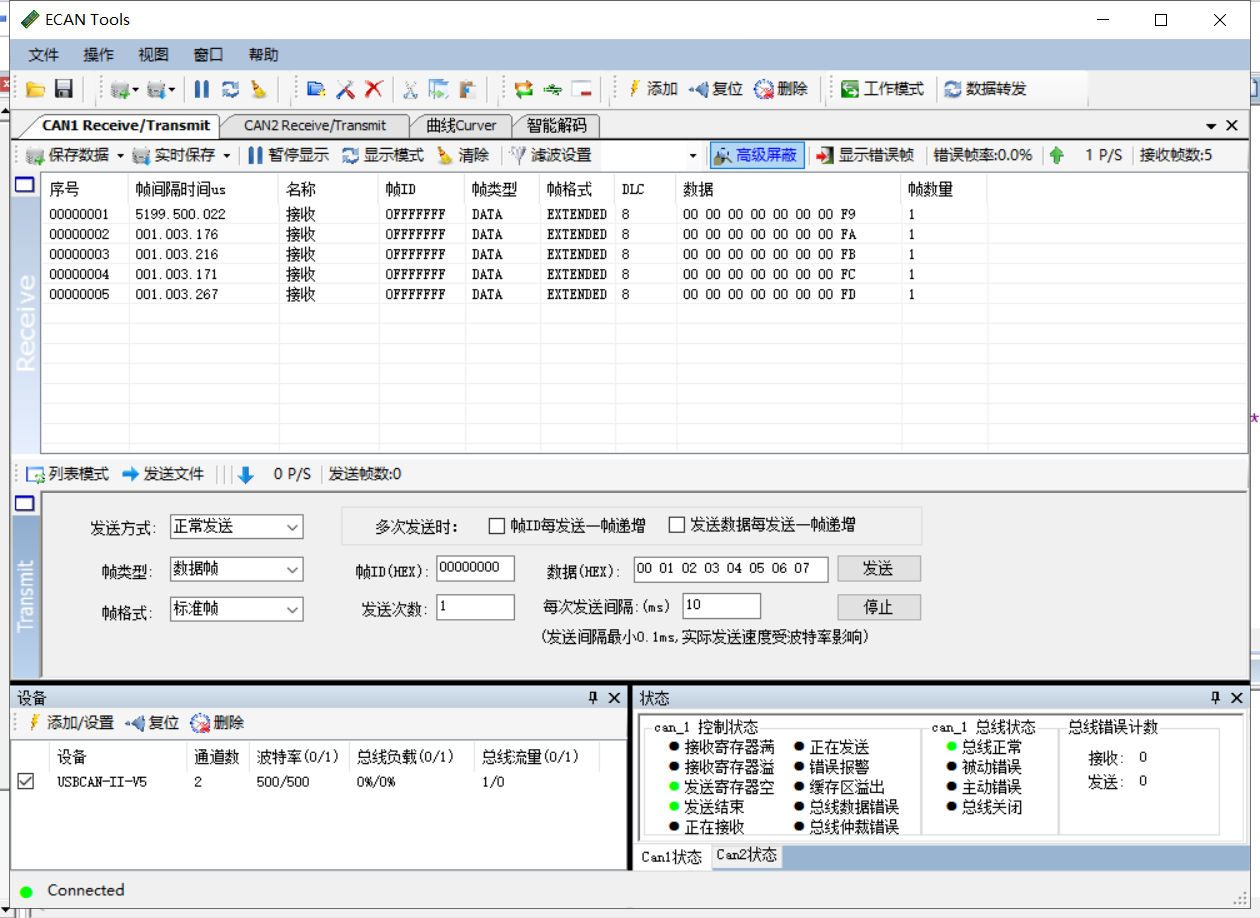
3. Commissioning results:
Project download connection: FDCAN_Send, click me to download!!!!!!
4, CAN accept
1. The filter type adopts mask mode:
1) Add the following function implementation:
FDCAN_RxHeaderTypeDef RxHeader;
uint8_t RxData[8];
void FDCAN1_Config(void)
{
  FDCAN_FilterTypeDef sFilterConfig;
  /* Configure Rx filter */
  sFilterConfig.IdType = FDCAN_EXTENDED_ID;
  sFilterConfig.FilterIndex = 1;
  sFilterConfig.FilterType = FDCAN_FILTER_MASK;
  sFilterConfig.FilterConfig = FDCAN_FILTER_TO_RXFIFO0;
  sFilterConfig.FilterID1 = 0x00000023;
  sFilterConfig.FilterID2 = 0x1FFFFFFF;

  if (HAL_FDCAN_ConfigFilter(&hfdcan1, &sFilterConfig) != HAL_OK)
  {
    Error_Handler();
  }

  sFilterConfig.IdType = FDCAN_EXTENDED_ID;
  sFilterConfig.FilterIndex = 0;
  sFilterConfig.FilterType = FDCAN_FILTER_MASK;
  sFilterConfig.FilterConfig = FDCAN_FILTER_TO_RXFIFO0;
  sFilterConfig.FilterID1 = 0x00000026;
  sFilterConfig.FilterID2 = 0x1FFFFFFF;

  if (HAL_FDCAN_ConfigFilter(&hfdcan1, &sFilterConfig) != HAL_OK)
  {
    Error_Handler();
  }

  /* Configure global filter:
     Filter all remote frames with STD and EXT ID
     Reject non matching frames with STD ID and EXT ID */
  if (HAL_FDCAN_ConfigGlobalFilter(&hfdcan1, FDCAN_REJECT, FDCAN_REJECT, FDCAN_FILTER_REMOTE, FDCAN_FILTER_REMOTE) != HAL_OK)
  {
    Error_Handler();
  }

  /* Start the FDCAN module */
  if (HAL_FDCAN_Start(&hfdcan1) != HAL_OK)
  {
    Error_Handler();
  }

  if (HAL_FDCAN_ActivateNotification(&hfdcan1, FDCAN_IT_RX_FIFO0_NEW_MESSAGE, 0) != HAL_OK)
  {
    Error_Handler();
  }

}

void HAL_FDCAN_RxFifo0Callback(FDCAN_HandleTypeDef *hfdcan, uint32_t RxFifo0ITs)
{
  if((RxFifo0ITs & FDCAN_IT_RX_FIFO0_NEW_MESSAGE) != RESET)
  {
    /* Retrieve Rx messages from RX FIFO0 */
    if (HAL_FDCAN_GetRxMessage(hfdcan, FDCAN_RX_FIFO0, &RxHeader, RxData) != HAL_OK)
    {
      Error_Handler();
    }
  }
}
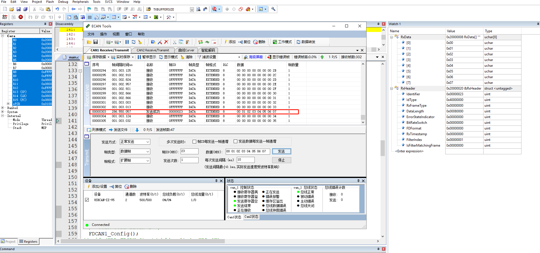
2) Commissioning results:
When the extension ID is sent 0x23, the data on the CAN bus will be sent to the CAN controller inside the single chip microcomputer through the filter with filter number 1.
When the extension ID is sent 0x26, the data on the CAN bus will be sent to the CAN controller inside the single chip microcomputer through the filter with filter number 2.
When the transmission extension ID is other, the data on the CAN bus will be filtered out by the filter and will not be sent to the CAN controller.
Project download connection: FDCAN_Receive_MASK, click me to download!!!!
summary
1. When the filter is selected as mask mode, that is, filtertype = fdcan_ FILTER_ The position of mask and FilterID2 is 0x1ffffffff, which means that all FilterID1 checks.
2. When multiple ID S need to be filtered, the number of filters used needs to be changed in CubeMX, otherwise it will be invalid, and the filter use order should be numbered. For example, suppose you assign two filters and use 0 and 2 in practice. Although 1 is not used, the actual effect should be that the 2 you assign is invalid and the 0 is valid.