preface
Our routing and switching final exam is a computer test, which uses eNSP to complete the test questions. The final examination questions are as follows. They are basically the same, with only a little change in details.
Finally, the PC host can ping each other, and the server can ping PC3 and PC3, but not PC1 and PC2.
Experimental requirements
The topology diagram is as follows:
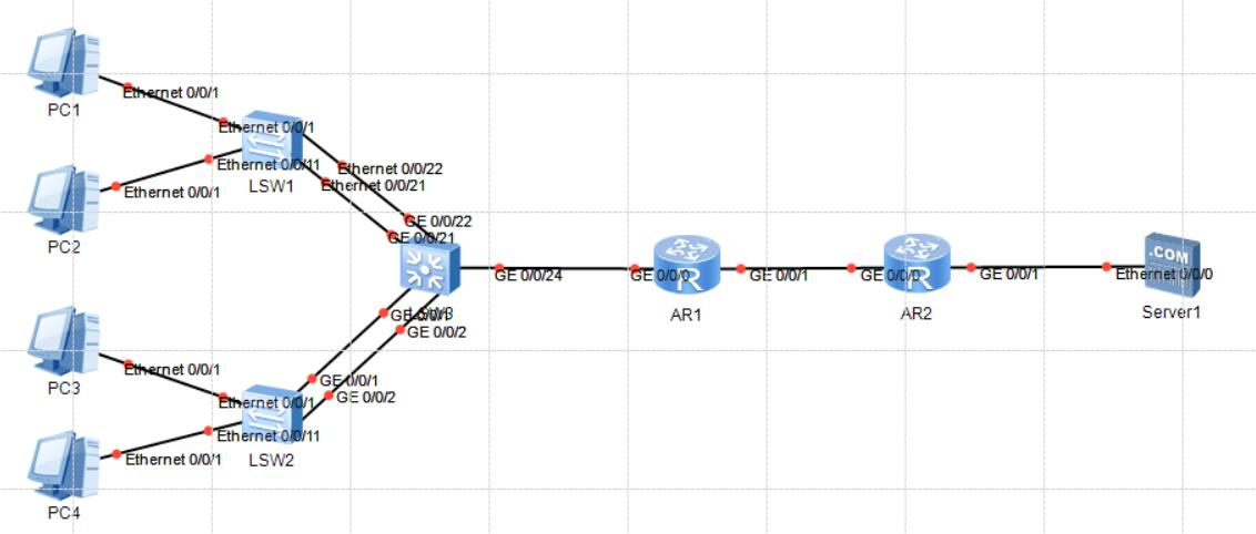
Connect the device interface according to the topology diagram, name the device and configure the IP address according to the following table.
| equipment | Interface | IP | connect | equipment | Interface | IP |
|---|---|---|---|---|---|---|
| PC1 | Eth0/0/1 | 10.10.10.10/24 | – | LSW1 | Eth0/0/1 | nothing |
| PC2 | Eth0/0/1 | 20.20.20.20/24 | – | LSW1 | Eth0/0/1 | nothing |
| PC3 | Eth0/0/1 | 30.30.30.30/24 | – | LSW2 | Eth0/0/1 | nothing |
| PC4 | Eth0/0/1 | 40.40.40.40/24 | – | LSW2 | Eth0/0/1 | nothing |
| LSW1 | Eth0/0/21 | nothing | – | LSW3 | GE0/0/21 | nothing |
| LSW1 | Eth0/0/22 | nothing | – | LSW3 | GE0/0/22 | nothing |
| LSW2 | GE0/0/1 | nothing | – | LSW3 | GE0/0/1 | nothing |
| LSW2 | GE0/0/2 | nothing | – | LSW3 | GE0/0/2 | nothing |
| LSW3 | VLANIF1 | 192.168.10.10/24 | – | AR1 | GE0/0/0 | 192.168.10.11/24 |
| AR1 | GE0/0/1 | 192.168.12.11/24 | – | AR2 | GE0/0/0 | 192.168.12.20/24 |
| AR2 | GE0/0/1 | 192.168.20.254/24 | – | Server1 | Eth0/0/0 | 192.168.20.20/24 |
- Create VLAN10 and VLAN20 on switch LSW1, and set VLANIF10 interface address to 10.10.10.253/24 and VLANIF20 interface address to 20.20.20.253/24. 9 points
- Create VLAN30 and VLAN40 on switch LSW2, and set VLANIF30 interface address to 30.30.30.253/24 and VLANIF40 interface address to 40.40.40.253/24. 9 points
- Create VLAN10, VLAN20, VLAN30 and VLAN40 on the switch LSW3, and set the VLANIF10 interface address to 10.10.10.254/24, the VLANIF20 interface address to 20.20.20.254/24, the VLANIF30 interface address to 30.30.30.254/24 and the VLANIF40 interface address to 40.40.40.254/24. VLANIF1 interface address is 192.168.10.10/24.
- The MTSP protocol configuration is completed between switch LSW1 and switch LSW3. The MST domain name is SR20181218, VLAN 10 is mapped to session 10, VLAN 20 is mapped to session 20, LSW1 is used as the main root bridge of VLAN 10 and the backup root bridge of VLAN 20; LSW3 serves as the primary root bridge of VLAN 20 and the backup root bridge of VLAN 10.
- The link aggregation configuration is completed between switch LSW2 and switch LSW3. The ETH trunk number is 1, and the load sharing mode is source MAC address and destination address, so as to realize the load sharing of traffic between each member interface of eth trunk.
- Configure RIP routing protocol on LSW3, AR1 and AR2, version 2, and complete the whole network connection.
- Configure the LSW3 core switch as a DHCP server, create two address pools for-net10 and for-net20, and assign IP addresses to the hosts of VLAN10 and VLAN20. The excluded addresses are 10.10.10.253 and 20.20.20.253 respectively.
- Create an access control list on AR2 with the number of 2000 and the rule step size of 5, i.e. 5, 10, 15; The planning sequence is as follows: (1) limit PC1 host; (2) Restrict PC2 host; (3) Others are allowed; And use this list on G0/0/0 port of AR2.
Detailed steps
1
Create VLAN10 and VLAN20 on switch LSW1, and set VLANIF10 interface address to 10.10.10.253/24 and VLANIF20 interface address to 20.20.20.253/24.
Command:
LSW1
# Create vlan10, 20:
vlan batch 10 20
# Set the interface address of vlanif10 and vlanif20:

interface Vlanif10
ip address 10.10.10.253 255.255.255.0

interface Vlanif20
ip address 20.20.20.253 255.255.255.0
2
Create VLAN30 and VLAN40 on switch LSW2, and set VLANIF30 interface address to 30.30.30.253/24 and VLANIF40 interface address to 40.40.40.253/24.
Command:
LSW2
# Create vlan10, vlan20
vlan batch 30 40
# Set the IP addresses of virtual interfaces vlanif30 and vlanif40

interface Vlanif30
ip address 30.30.30.253 255.255.255.0

interface Vlanif40
ip address 40.40.40.253 255.255.255.0
3
Create VLAN10, VLAN20, VLAN30 and VLAN40 on the switch LSW3, and set the VLANIF10 interface address to 10.10.10.254/24, the VLANIF20 interface address to 20.20.20.254/24, the VLANIF30 interface address to 30.30.30.254/24 and the VLANIF40 interface address to 40.40.40.254/24. VLANIF1 interface address is 192.168.10.10/24.
Command:
LSW3
# Create vlan10, 20, 30, 40
vlan batch 10 20 30 40
# Set the interface addresses of virtual interfaces vlanif1, 10, 20, 30 and 40

interface Vlanif1
ip address 192.168.10.10 255.255.255.0

interface Vlanif10
ip address 10.10.10.254 255.255.255.0
dhcp select global         //Set DHCP global based configuration

interface Vlanif20
ip address 20.20.20.254 255.255.255.0
dhcp select global         //Set DHCP global based configuration

interface Vlanif30
ip address 30.30.30.254 255.255.255.0
dhcp select global         //Set DHCP global based configuration

interface Vlanif40
ip address 40.40.40.254 255.255.255.0
dhcp select global         //Set DHCP global based configuration
4
Complete the MSTP protocol configuration between switch LSW1 and switch LSW3. The MST domain name is SR20181218, VLAN 10 is mapped to session 10, VLAN 20 is mapped to session 20, LSW1 is used as the primary root bridge of VLAN 10 and the backup root bridge of VLAN 20; LSW3 serves as the primary root bridge of VLAN 20 and the backup root bridge of VLAN 10.
Command:
[LSW1] MTSP protocol configuration:
stp region-configuration   //Enter MSTP domain view
region-name SR20181218  //Specify the MST domain name as SR20181218
instance 10 vlan 10    //Mapping Session 10 of VLAN 10
instance 20 vlan 20    //Mapping session 20 of VLAN 20

active region-configuration //Activate the above configuration
[LSW1] vlan partition edge port setting of physical interface
interface Ethernet0/0/1
port link-type access
port default vlan 10   //Add E0/0/0 interface to vlan 10
stp edged-port enable   //**Set the interface as an edge port**

interface Ethernet0/0/11
port link-type access   //Note that the eth interface setting here is access mode
port default vlan 20
stp edged-port enable   //**Ibid**

interface Ethernet0/0/21
port link-type trunk
port trunk allow-pass vlan 2 to 4094

interface Ethernet0/0/22
port link-type trunk
port trunk allow-pass vlan 2 to 4094   //Configure the vlan id allowed by trunk
[LSW3] MTSP protocol configuration:
stp region-configuration
region-name SR20181218
instance 10 vlan 10
instance 20 vlan 20

active region-configuration
[LSW3] STP configuration of root bridge and standby bridge of VLAN 10 and 20
stp instance 10 root secondary  //Set the backup bridge of vlan10
stp instance 20 root primary   //Set the root bridge of VLAN 20

//LSW1 sets the edge path, so it will participate in the election
5
The link aggregation configuration is completed between switch LSW2 and switch LSW3. The ETH trunk number is 1, and the load sharing mode is source MAC address and destination address, so as to realize the load sharing of traffic between each member interface of eth trunk.
Command:
[LSW2] configuration of link aggregation and load balancing
interface Eth-Trunk1   //Create eth trunk link aggregation port, number 1
port link-type trunk
port trunk allow-pass vlan 2 to 4094   //**The configuration of trunk * * * * interface needs to be set**
load-balance src-dst-mac   //Configure normal load sharing. The type is mac or destination address

interface GigabitEthernet0/0/1
eth-trunk 1            //Add G0/0/1 to eth trunk 1

interface GigabitEthernet0/0/2
eth-trunk 1            //The same as above, so the two ports do not need to display the specified IP
[LSW2] relevant configuration of each interface
interface Ethernet0/0/1
port link-type access
port default vlan 30   //E0/0/1 interface setting default vlan 30
stp edged-port enable   //And set the interface as an edge port

interface Ethernet0/0/11
port link-type access
port default vlan 40
stp edged-port enable   //Ibid
[LSW3] configuration of link aggregation and load balancing
interface Eth-Trunk1
port link-type trunk
port trunk allow-pass vlan 2 to 4094
load-balance src-dst-mac

interface GigabitEthernet0/0/1
eth-trunk 1

interface GigabitEthernet0/0/2
eth-trunk 1
[LSW3] IP configuration of other interfaces and id allowed by vlan
interface GigabitEthernet0/0/21
port link-type trunk
port trunk allow-pass vlan 2 to 4094

interface GigabitEthernet0/0/22
port link-type trunk
port trunk allow-pass vlan 2 to 4094

interface GigabitEthernet0/0/24
port link-type trunk
port trunk allow-pass vlan 2 to 4094
6
Configure RIP routing protocol on LSW3, AR1 and AR2, version 2, and complete the whole network connection.
Command:
[LSW3] RIP routing protocol configuration, set to version 2
rip 1       //Enable RIP process 1
undo summary    //Disable route summary function
version 2     //Enable version 2
network 10.0.0.0
network 20.0.0.0
network 30.0.0.0
network 40.0.0.0
network 192.168.10.0   //Announce the main network address, all of which are
[AR1] RIP routing protocol configuration, set to version 2
rip 1
undo summary
version 2
network 192.168.12.0
network 192.168.10.0   //Note 10 here
[AR2] RIP routing protocol configuration, set to version 2
rip 1
undo summary
version 2
network 192.168.12.0
network 192.168.20.0   //Note 20 here
7
Configure the LSW3 core switch as a DHCP server, create two address pools for-net10 and for-net20, and assign IP addresses to the hosts of VLAN10 and VLAN20 (the actual four address pools), in which the excluded addresses are 10.10.10.253 and 20.20.20.253 respectively.
DHCP configuration of [LSW3]
ip pool for-net10   //Create global address pool for-net10
gateway-list 10.10.10.254   //Configure exit gateway address for DHCP client
network 10.10.10.0 mask 255.255.255.0  //Configure the network segment addresses that can be allocated by the address pool
excluded-ip-address 10.10.10.253 //Configure IP addresses in the IP address pool that do not participate in automatic allocation

ip pool for-net20
gateway-list 20.20.20.254
network 20.20.20.0 mask 255.255.255.0
excluded-ip-address 20.20.20.253

ip pool for-net30
gateway-list 30.30.30.254
network 30.30.30.0 mask 255.255.255.0
excluded-ip-address 30.30.30.253

ip pool for-net40
gateway-list 40.40.40.254
network 40.40.40.0 mask 255.255.255.0
excluded-ip-address 40.40.40.253
8
Create an access control list on AR2 with the number of 2000 and the rule step size of 5, i.e. 5, 10, 15; The planning sequence is as follows: (1) limit PC1 host; (2) Restrict PC2 host; (3) Others are allowed; And use this list on G0/0/0 port of AR2.
Command:
acl number 2000      //Create ACL access control list
//The specified step size rule is 5 and the limit is PC1
rule 5 deny source 10.10.10.10 0
//The specified step size rule is 10 and the limit is PC2
rule 10 deny source 20.20.20.20 0
//Messages with step size of 15 are allowed to pass
rule 15 permit

interface GigabitEthernet0/0/0
ip address 192.168.12.20 255.255.255.0
//Specify to configure ACL message filtering in the incoming direction of the interface
traffic-filter inbound acl 2000

interface GigabitEthernet0/0/1
ip address 192.168.20.254 255.255.255.0
Full command
LSW1
system-view
sysname LSW1

vlan batch 10 20
interface vlanif10
	ip address 10.10.10.253 255.255.255.0
interface vlanif20
	ip address 20.20.20.253 255.255.255.0
quit

stp region-configuration
	region-name SR20181218
    instance 10 vlan 10
    instance 20 vlan 20
    active region-configuration
stp instance 20 root secondary
stp instance 10 root primary

interface Ethernet0/0/1
    port link-type access
    port default vlan 10
    stp edged-port enable

interface Ethernet0/0/11
    port link-type access
    port default vlan 20
    stp edged-port enable

interface Ethernet0/0/21
    port link-type trunk
    port trunk allow-pass vlan 2 to 4094

interface Ethernet0/0/22
    port link-type trunk
    port trunk allow-pass vlan 2 to 4094
LSW2
system-view
sysname LSW2

vlan batch 30 40
interface vlanif30
	ip address 30.30.30.253 255.255.255.0
interface vlanif40
	ip address 40.40.40.253 255.255.255.0

interface Eth-Trunk1
    port link-type trunk
    port trunk allow-pass vlan 2 to 4094
	load-balance src-dst-mac
quit

interface GigabitEthernet0/0/1
	eth-trunk 1
interface GigabitEthernet0/0/2
	eth-trunk 1

interface Ethernet0/0/1
    port link-type access
    port default vlan 30
    stp edged-port enable

interface Ethernet0/0/11
    port link-type access
    port default vlan 40
    stp edged-port enable
LSW3
system-view
sysname LSW3

vlan batch 10 20 30 40
interface vlanif10
	ip address 10.10.10.254 255.255.255.0
interface vlanif20
	ip address 20.20.20.254 255.255.255.0
interface vlanif30
	ip address 30.30.30.254 255.255.255.0
interface vlanif40
	ip address 40.40.40.254 255.255.255.0
interface vlanif1
	ip address 192.168.10.10 255.255.255.0
quit


stp region-configuration
region-name SR20181218
    instance 10 vlan 10
    instance 20 vlan 20
    active region-configuration
stp instance 10 root secondary
stp instance 20 root primary

interface Eth-Trunk1
    port link-type trunk
    port trunk allow-pass vlan 2 to 4094
    load-balance src-dst-mac
quit

interface GigabitEthernet0/0/1
	eth-trunk 1
interface GigabitEthernet0/0/2
	eth-trunk 1

rip
    version 2
    network 10.0.0.0
    network 20.0.0.0
    network 30.0.0.0
    network 40.0.0.0
    network 192.168.10.0
    undo summary
quit

ip pool for-net10
    gateway-list 10.10.10.254
    network 10.10.10.0 mask 255.255.255.0
    excluded-ip-address 10.10.10.253
quit
ip pool for-net20
    gateway-list 20.20.20.254
    network 20.20.20.0 mask 255.255.255.0
    excluded-ip-address 20.20.20.253
quit
ip pool for-net30
    gateway-list 30.30.30.254
    network 30.30.30.0 mask 255.255.255.0
    excluded-ip-address 30.30.30.253
quit
ip pool for-net40
    gateway-list 40.40.40.254
    network 40.40.40.0 mask 255.255.255.0
    excluded-ip-address 40.40.40.253
dhcp enable

interface Vlanif10
	dhcp select global

interface Vlanif20
	dhcp select global

interface Vlanif30
	dhcp select global

interface Vlanif40
	dhcp select global

interface GigabitEthernet0/0/21
    port link-type trunk
    port trunk allow-pass vlan 2 to 4094

interface GigabitEthernet0/0/22
    port link-type trunk
    port trunk allow-pass vlan 2 to 4094

interface GigabitEthernet0/0/24
    port link-type trunk
    port trunk allow-pass vlan 2 to 4094
AR1
system-view
sysname AR1
 rip 1
    version 2
    network 192.168.12.0
    network 192.168.10.0
    undo summary

interface GigabitEthernet0/0/0
	ip address 192.168.10.11 255.255.255.0

interface GigabitEthernet0/0/1
	ip address 192.168.12.11 255.255.255.0
AR2
system-view
sysname AR2
rip 1
    undo summary
    version 2
    network 192.168.12.0
    network 192.168.20.0
quit
acl number 2000
    rule 5 deny source 10.10.10.10 0
    rule 10 deny source 20.20.20.20 0
    rule 15 permit
quit

interface GigabitEthernet0/0/0
    ip address 192.168.12.20 255.255.255.0
	traffic-filter inbound acl 2000

interface GigabitEthernet0/0/1
    ip address 192.168.20.254 255.255.255.0
summary
This experiment is not difficult, but slightly cumbersome. Each interface needs to be configured, and the details are very important.
After today's test, my dear teacher is sincere and doesn't deceive me. The test topic is just changing the IP address, changing RIP to OSPF, and adding AR3 between AR2 and the server.