I'm afraid that there is no star sea in my office at home: playing like a running water lamp!
The flow light understood by Xiaobian is a group of LED lights, which can be turned on and off according to the set style under the control of the system, thus forming a certain visual effect.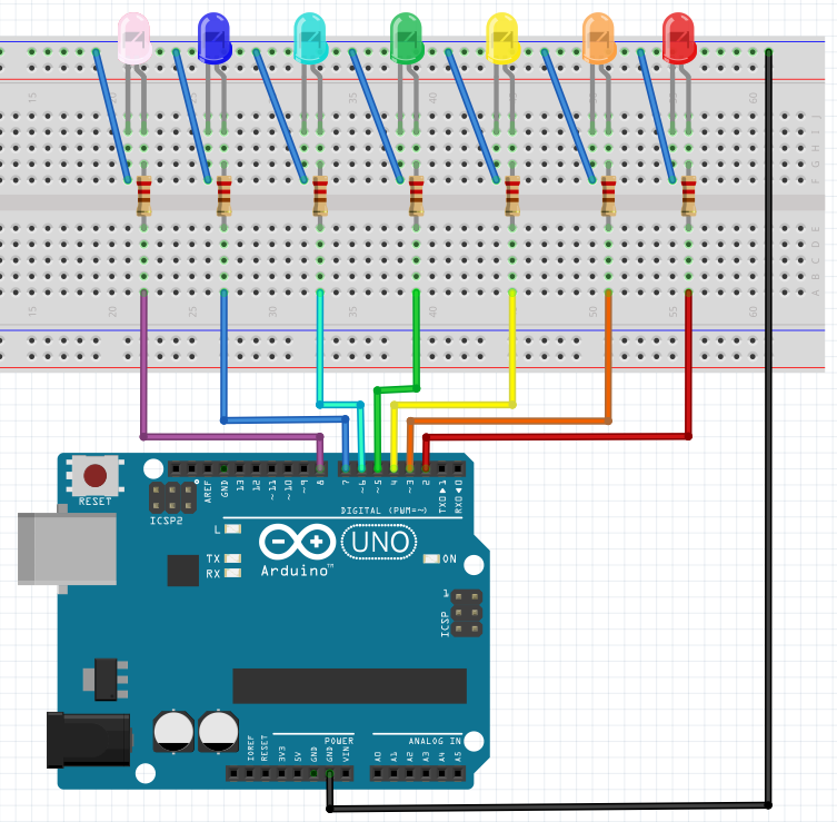
In the circuit, connect the negative pole (shorter pin) of 7 LED lights to GND, and connect the positive pole (longer pin) of led through resistance to 2 ~ 8 pins of Arduino. Pay attention not to use 0 and 1 pins of Arduino as much as possible (these two pins are mainly used for serial communication, and also used when uploading programs).
Why must the positive pole of LED light be connected with resistance? Is this connection current filling or current pulling? I can't remember the children's shoes. Go to the last article of Xiaobian.
Style 1
Seven LED lights flash at the same time. Although we seem to be at the same time, one of the programs is still on, but the program execution is very fast, and our eyes can't see the interval.
void setup() {
  //Set pin 2-8 as output mode
  pinMode(2, OUTPUT);
  pinMode(3, OUTPUT);
  pinMode(4, OUTPUT);
  pinMode(5, OUTPUT);
  pinMode(6, OUTPUT);
  pinMode(7, OUTPUT);
  pinMode(8, OUTPUT);
}
void loop() {
  for (int i = 2; i <= 8; i++) {//for loop, using variable i to represent pin 2-8 of Arduino
    digitalWrite(i, HIGH);//Set pin i output high level to light LED
  }
  delay(300);//Delay 300 ms, can be changed according to the flashing effect
  for (int i = 2; i <= 8; i++) {//loop
    digitalWrite(i, LOW);//Set pin i output low level to turn off LED
  }
  delay(300);//Delay 300 ms
}
Style two
7 LED lights, from both ends to the middle, then from the middle to both ends
void setup() {
  pinMode(2, OUTPUT);
  pinMode(3, OUTPUT);
  pinMode(4, OUTPUT);
  pinMode(5, OUTPUT);
  pinMode(6, OUTPUT);
  pinMode(7, OUTPUT);
  pinMode(8, OUTPUT);
}
int k;
void loop() {
  k = 2;//Define variable, value 2 represents pin 2
  int q =8;//Define variable, value 8 represents pin 8
  while (k <= 8)//Executing a while loop when the value of k is less than 8
  {
    digitalWrite(k, HIGH);//Pin k output high level, light up the LED connected to the corresponding pin
    digitalWrite(q, HIGH);//Pin q output high level, light up the LED connected to the corresponding pin
    delay(300);//Appropriate delay, with the effect of delay lighting
    digitalWrite(k, LOW);//Pin k output low level, turn off the LED connected to the corresponding pin
    digitalWrite(q, LOW);//Pin k output low level, turn off the LED connected to the corresponding pin
    k++;//k from 2 to 8
    q--;//q from 8 to 2
  }
}
Style three
1. Light up one by one
7 LED lights, one by one
void setup() {
  pinMode(2, OUTPUT);
  pinMode(3, OUTPUT);
  pinMode(4, OUTPUT);
  pinMode(5, OUTPUT);
  pinMode(6, OUTPUT);
  pinMode(7, OUTPUT);
  pinMode(8, OUTPUT);
}
int k;//Define variable, representing pin number
void loop() {
    k = 2;//Pin from 2
    while (k <= 8)
    {
      digitalWrite(k, HIGH);
      delay(300);
      digitalWrite(k, LOW);
      k++;
    }
}
2. Two on
Seven LED lights, two lights, logic is the same as one lights.
void setup() {
  pinMode(2, OUTPUT);
  pinMode(3, OUTPUT);
  pinMode(4, OUTPUT);
  pinMode(5, OUTPUT);
  pinMode(6, OUTPUT);
  pinMode(7, OUTPUT);
  pinMode(8, OUTPUT);
}
int k;//Define variable, representing pin number
void loop() {
    k = 2;//Pin from 2
    while (k <= 8)
    {
      digitalWrite(k, HIGH);//Turn on the k LED
      digitalWrite(k - 1, HIGH);//At the same time, turn on the k-1 LED, that is, the one in front of the K pin
      delay(300);//delayed
      digitalWrite(k - 1, LOW);//Turn off the k-1 LED
      k++;//k increases from 2 to 8
    }
    delay(300);//delayed
    digitalWrite(k - 1, LOW);//Turn off the last LED
    delay(300);//delayed
}
3. Difficulty upgrading
Seven LED lights, one on, two on, three on, and Until all 7 lights up, repeat the process.
I feel so hard!!! In fact, when we finish a program with one light and two lights, we just need to find out the rules in the program, but we will nest loop statements and define several more variables.
void setup() {
  pinMode(2, OUTPUT);
  pinMode(3, OUTPUT);
  pinMode(4, OUTPUT);
  pinMode(5, OUTPUT);
  pinMode(6, OUTPUT);
  pinMode(7, OUTPUT);
  pinMode(8, OUTPUT);
}
int k, deg, i;//Defining variables
void loop() {
  deg = 1;//Mark several LED lights on at a time
  while (deg <= 7)//7 LED lights in total
  {
    k = 2;//For pin 2
    while (k <= 8)
    {
      i = 0;//There are several LED lights to be on / off in front of k
      while (i < deg)
      {
        digitalWrite(k - i, HIGH);//Turn on the k-i LED, i.e. the i-th LED in front of the K
        i++;
      }
      delay(300);
      digitalWrite(k - deg + 1, LOW);//Turn off the LED light k-(deg-1)
      k++;
    }
    i = deg - 1;//At last, several LED lights need to be turned off separately
    while (i > 0)
    {
      delay(300);
      digitalWrite(k - i, LOW);//Turn off the k-i LED
      i--;
    }
    delay(300);
    deg++;//deg plus 1, prepare to light several LED lights in the next cycle
  }
}
Comprehensive display effect
Write the above patterns into a program. First let seven LED lights flash, then light them from both ends to the middle, then light them in turn, and finally add some music. It's more fun.
void setup() {
  pinMode(2, OUTPUT);
  pinMode(3, OUTPUT);
  pinMode(4, OUTPUT);
  pinMode(5, OUTPUT);
  pinMode(6, OUTPUT);
  pinMode(7, OUTPUT);
  pinMode(8, OUTPUT);
}
int k, deg, i;//Defining variables
void loop() {
  for (int j = 0; j < 3; j++)//Flash three times first
  {
    for (int i = 2; i <= 8; i++) {//for loop, using variable i to represent pin 2-8 of Arduino
      digitalWrite(i, HIGH);//Set pin i output high level to light LED
    }
    delay(300);//Delay 300 ms, can be changed according to the flashing effect
    for (int i = 2; i <= 8; i++) {//loop
      digitalWrite(i, LOW);//Set pin i output low level to turn off LED
    }
    delay(300);//Delay 300 ms
  }
  k = 2;//Define variable, value 2 represents pin 2
  int q = 8; //Define variable, value 8 represents pin 8
  while (k <= 8)//Executing a while loop when the value of k is less than 8
  {
    digitalWrite(k, HIGH);//Pin k output high level, light up the LED connected to the corresponding pin
    digitalWrite(q, HIGH);//Pin q output high level, light up the LED connected to the corresponding pin
    delay(300);//Proper delay, with the effect of delay lighting
    digitalWrite(k, LOW);//Pin k output low level, turn off the LED connected to the corresponding pin
    digitalWrite(q, LOW);//Pin k output low level, turn off LED connected to corresponding pin
    k++;//k from 2 to 8
    q--;//q from 8 to 2
  }
  deg = 1;//Mark several LED lights on at a time
  while (deg <= 7)//7 LED lights in total
  {
    k = 2;//For pin 2
    while (k <= 8)
    {
      i = 0;//There are several LED lights to be on / off in front of k
      while (i < deg)
      {
        digitalWrite(k - i, HIGH);//Turn on the k-i LED, i.e. the i-th LED in front of the K
        i++;
      }
      delay(300);
      digitalWrite(k - deg + 1, LOW);//Turn off the LED light k-(deg-1)
      k++;
    }
    i = deg - 1;//At last, several LED lights need to be turned off separately
    while (i > 0)
    {
      delay(300);
      digitalWrite(k - i, LOW);//Turn off the k-i LED
      i--;
    }
    delay(300);
    deg++;//deg plus 1, prepare to light several LED lights in the next cycle
  }
}
About the Arduino control of the water light case to share these, you have more fun water light case? If so, please leave a message to tell the editor. For more exciting case, please pay attention to Xiaobian's official account of WeChat.