Using FPGA to build a state machine to control the light on and off, so as to understand the practical application of state machine.
1. Routine introduction:
Suppose there is an input data stream, this data stream will input a ~ Z or a ~ Z letters arbitrarily, and "hello" will be input successively at a certain time. Now design a state machine. When Hello is detected, the LED light turns on and off.
2. Design analysis:
The whole detection process can be divided into the following states:
1. Wait for H to arrive. If h is detected, enter 2 to start detecting e, otherwise wait for h all the time;
2. Check whether it is e. if it is e - > enter 3 and start to detect l. if it is not e - > Return 1 and continue to wait for H;
3. Check whether it is l. if it is l - > enter 4 and start to detect l. if it is not l - > Return 1 and continue to wait for H;
4. Check whether it is l. if it is l - > enter 5 and start to detect o. if it is not l - > Return 1 and continue to wait for H;
5. Check whether it is o. if it is o - > enter 6 and start to detect w. if it is not o - > Return 1 and continue to wait for H;
6. Check whether it is w, if it is w - > flip the LED and return to 1 to wait for the next h; If not w - > Return 1 and continue to wait for H;
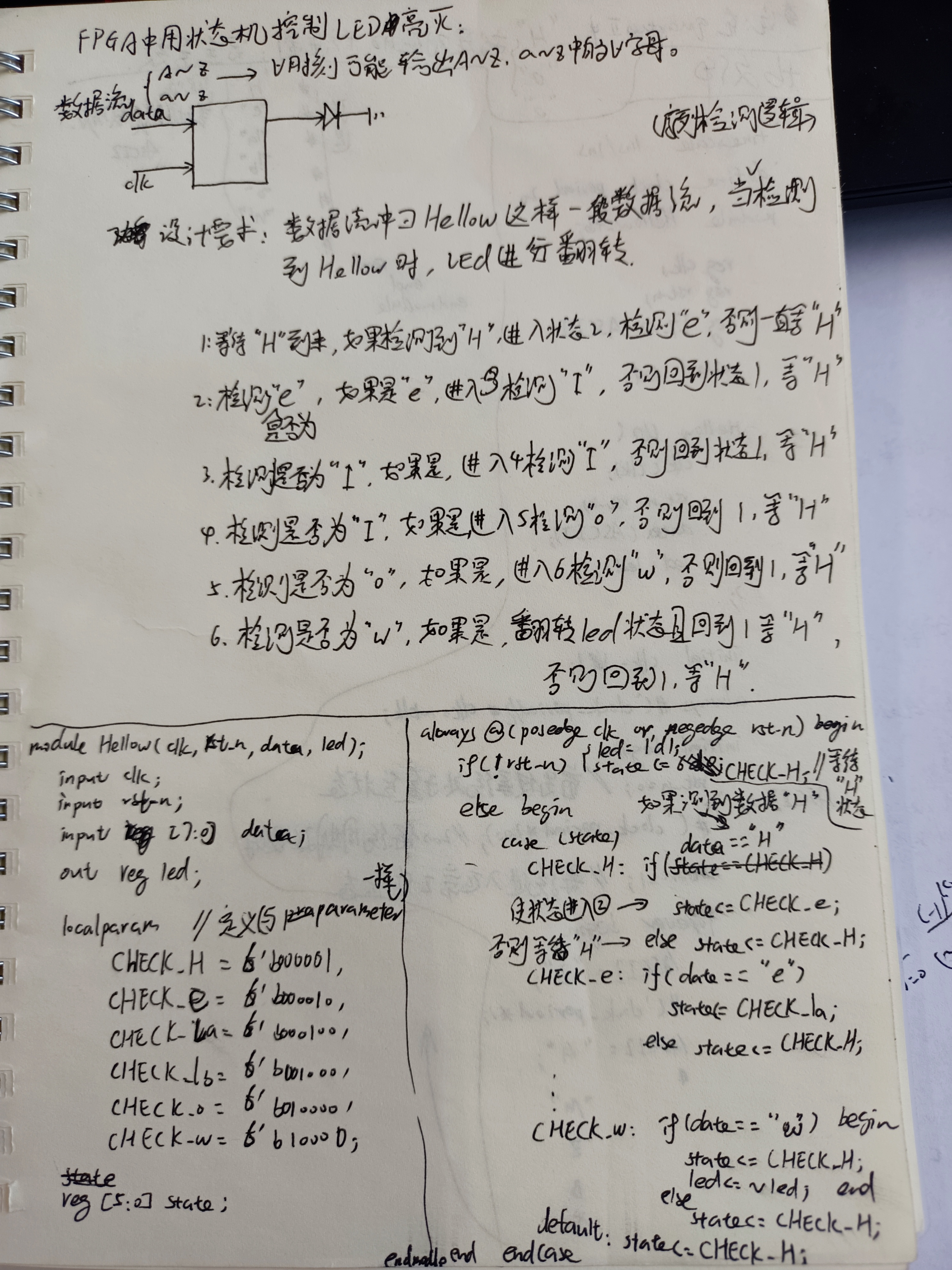
3.rtl procedure:
module Hellow(clk50M,rst_n,data,led);

	input clk50M;
	input rst_n;
	input [7:0] data;                              //The input data stream is an 8-bit binary ASCII code
	output reg led;

	reg [5:0] state;                               //Each state uses a single hot code with low coding density. There are six states, so six bits are enough

	localparam                                     //Define the unique heat code corresponding to the state so that it can be called in the case statement (localparam usage is the same as parameter).
		CHECK_H=6'b000001,
		CHECK_e=6'b000010,
		CHECK_la=6'b000100,
		CHECK_lb=6'b001000,
		CHECK_o=6'b010000,
		CHECK_w=6'b100000;

	always @ (posedge clk50M or negedge rst_n) begin

		if(!rst_n) begin					       //When resetting, the LED is off and the status is 1 "waiting for H"
			led<=1'd0;
			state<=CHECK_H;
		end

		else begin
			case(state)						       //The case statement detects what state it belongs to
			CHECK_H:                	           //For example: when it is CHECK_H state
					if(data=="H")                  //Each time you enter a data, judge whether data is H
						state<=CHECK_e;	           //If yes - > enter the next state
					else
						state<=CHECK_H;	           //If not - > return CHECK_H state
				CHECK_e:
					if(data=="e")
						state<=CHECK_la;
					else
						state<=CHECK_H;
				CHECK_la:
					if(data=="l")
						state<=CHECK_lb;
					else
						state<=CHECK_H;
				CHECK_lb:
					if(data=="l")
						state<=CHECK_o;
					else
						state<=CHECK_H;
				CHECK_o:
					if(data=="o")
						state<=CHECK_w;
					else
						state<=CHECK_H;
				CHECK_w:
					if(data=="w") begin
						led<=~led;
						state<=CHECK_H;
					end
					else
						state<=CHECK_H;
				default:
					state<=CHECK_H;
			endcase
		end
	end
endmodule
be careful:
Finally, add default to avoid the latch latch caused by no corresponding output of the input; The 6-bit single hot code only uses 6 values. When state is other values, execute the statement after default.
4.testbench test file:
`timescale 1ns/1ps
`define clock_period 20
module Hellow_tb;

	reg clk;
	reg rst_n;
	reg [7:0] ASCII;
	wire led;

	Hellow Hellow1(
		.clk50M(clk),
		.rst_n(rst_n),
		.data(ASCII),
		.led(led)
	);

	initial clk=1;
	always #(`clock_period/2) clk=~clk;
	initial begin
		rst_n=0;
		ASCII=0;
		#(`clock_period*200);
		rst_n=1;
		forever begin
			ASCII="a";                       //abc
			#(`clock_period);
			ASCII="b";
			#(`clock_period);
			ASCII="c";
			#(`clock_period);


			ASCII="H";                       //Hellow
			#(`clock_period);
			ASCII="e";
			#(`clock_period);
			ASCII="l";
			#(`clock_period);
			ASCII="l";
			#(`clock_period);
			ASCII="o";
			#(`clock_period);
			ASCII="w";
			#(`clock_period);
		end
	end
endmodule
be careful:
1. When setting the simulation data flow here, an interference data (abc) is set to check whether only Hello can realize the state machine function;
2. When initializing the excitation data flow, the forever statement is used, and the program will run all the time; We need to manually set the simulation time in the configuration modelsim;
3. "H" in quartus is completely equivalent to hexadecimal data 0x48 corresponding to capital H.
5. Waveform diagram:

The above figure shows the flip of the LED.

As can be seen from the previous simulation in the figure above, each flip is aligned with the rising edge of the clock.
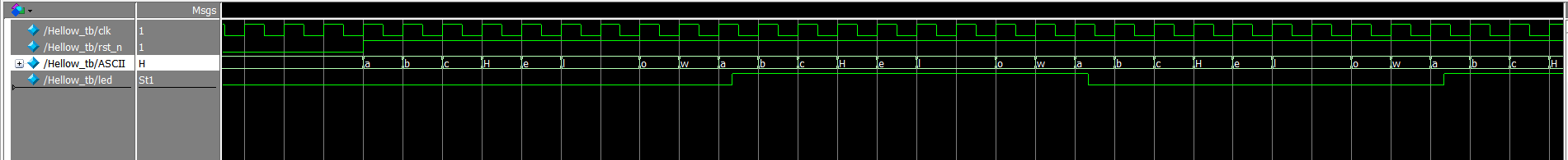
After the above figure, the simulation can observe the real situation. Each time w is detected, the LED of the next beat turns over.