The interrupt configuration of FreeRTOS is a very important content, which needs to be configured according to the MCU used. This requires knowledge about interrupts in MCU architecture. This paper explains the FreeRTOS interrupt configuration under STM32 platform in combination with Cortex-M's NVIC, which is divided into the following parts:
1. Cortex-M interrupt
2. FreeRTOS interrupt configuration macro
3. FreeRTOS switch interrupt
4. Critical segment code
5. FreeRTOS interrupt test experiment
1. Cortex-M interrupt
The MCU of Cortex-M kernel (STM32) provides a nested vector interrupt controller (NVIC) for interrupt management. The NVIC of Cotex-M3 supports up to 240 IRQs (interrupt requests), 1 non maskable interrupt (NMI), 1 systick timer interrupt and multiple system exceptions.
Cortex-M processor has several programmable registers for managing interrupts and exceptions. Most of these registers are in NVIC and system control block (SCB). CMSIS defines these registers as structures. Take STM32F103 as an example, open the core_cm3.h. There are two structures, NVIC_Type and SCB_Type, which stores this information.
Priority group definition
When multiple interrupts come, which interrupt the processor should respond to is determined by the interrupt priority. High priority interrupts (small priority number) must be responded first, and high priority interrupts can preempt low priority interrupts, which is interrupt nesting.
Some interrupts of Cortex-M processor have fixed priority, such as reset, NMI and HardFault. The priority of these interrupts is negative and the priority is the highest.
Cortex-M processor has three fixed priorities and 256 programmable priorities, with a maximum of 128 preemption levels, but the actual number of priorities is determined by the chip manufacturer. However, the vast majority of chips will simplify the design, so that they actually support fewer priority levels, such as level 8, level 16, level 32, etc. for example, STM32 has only level 16 priority.
2. FreeRTOS interrupt configuration macro
1,configPRIO_BITS: sets the priority of several bits used by MCU. STM32 uses 4 bits, so this macro is 4
2,configLIBRARY_LOWEST_INTERRUPT_PRIORITY: set the lowest priority.
3,configKERNEL_INTERRUPT_PRIORITY: this macro is used to set the kernel interrupt priority.
4,configLIBRARY_MAX_SYSCALL_INTERRUPT_PRIORITY: to set the maximum priority that the FreeRTOS system can manage. The priority higher than x is not managed by FreeRTOS!
5,configMAX_SYSCALL_INTERRUPT_PRIORITY: interrupts lower than this priority can safely call FreeRTOS API functions. Interrupts higher than this priority cannot be prohibited, and interrupt service functions cannot call FreeRTOS API functions!
3. FreeRTOS switch interrupt
The FreeRTOS switch interrupt function is portENABLE_INTERRUPTS() and portDISABLE_INTERRUPTS(), which are actually macro definitions in portmacro H is defined as follows:
#define portDISABLE_INTERRUPTS()    vPortRaiseBASEPRI()
#define portENABLE_INTERRUPTS()    vPortSetBASEPRI(0)
It can be seen that the switch interrupt is actually realized through the functions vPortSetBASEPRI(0) and vportraisebaseri ().
The function vPortSetBASEPRI() writes a value to the register BASEPRI, which is passed in as the parameter ulBASEPRI, portENABLE_INTERRUPTS() is an interrupt. It passes a 0 to vportsetbasepri (). According to the BASEPRI register we explained earlier, the result is an interrupt.
The function vportraisebaepri() writes the macro configmax to the register baseepri_ SYSCALL_ INTERRUPT_ Priority, then the priority is lower than configMAX_SYSCALL_INTERRUPT_PRIORITY interrupts will be masked!
4. Critical segment code
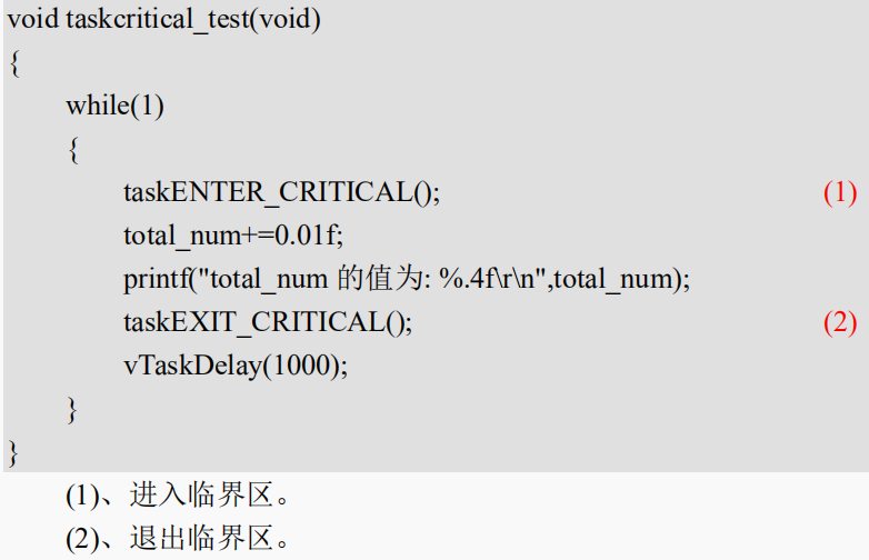
Critical segment code, also known as critical area, refers to those code segments that must run completely and cannot be interrupted. For example, the initialization of some peripherals requires strict timing and cannot be interrupted during initialization. FreeRTOS needs to close the interrupt when entering the critical segment code, and then open the interrupt after processing the critical segment code. FreeRTOS system itself has a lot of critical segment code. These codes are protected by critical segment code. We also need to add critical segment code protection in some places when writing our own user programs.
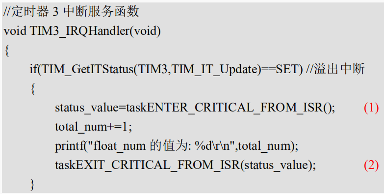
FreeRTOS has four functions related to critical segment code protection: taskENTER_CRITICAL() ,taskEXIT_CRITICAL() , taskENTER_CRITICAL_FROM_ISR() and taskEXIT_CRITICAL_FROM_ISR(), these four functions are actually macro definitions in task H is defined in the document. The difference between these four functions is that the first two are critical segment code protection at task level and the last two are critical segment code protection at interrupt level.
The use method of task level critical code protection is as follows:
The use method of interrupt level critical code protection is as follows:
5. FreeRTOS interrupt test experiment
Setting: priority in FreeRTOS is lower than configMAX_SYSCALL_INTERRUPT_PRIORITY interrupts will be masked, and those higher than will not, so let's write a simple routine to test.
Two timers are used, one priority is 4 and the other priority is 5. The two timers output a string through the serial port every 1s. Then turn off the interrupt for a period of time in a task and check the output of the two timers.
main.c
#include "sys.h"
#include "delay.h"
#include "usart.h"
#include "led.h"
#include "timer.h"
#include "FreeRTOS.h"
#include "task.h"

#define START_TASK_PRIO   1
#define START_STK_SIZE    256
TaskHandle_t StartTask_Handler;
void start_task(void *pvParameters);

#define INTERRUPT_TASK_PRIO  2
#define INTERRUPT_STK_SIZE   256
TaskHandle_t INTERRUPTTask_Handler;
void interrupt_task(void *p_arg);

int main(void)
{
 NVIC_PriorityGroupConfig(NVIC_PriorityGroup_4);
 delay_init();
 uart_init(115200);
 LED_Init();
 //Start two timers and print continuously unless the interrupt is turned off
 TIM3_Int_Init(10000-1,7200-1);
 TIM5_Int_Init(10000-1,7200-1);

    xTaskCreate((TaskFunction_t )start_task,
                (const char*    )"start_task",
                (uint16_t       )START_STK_SIZE,
                (void*          )NULL,
                (UBaseType_t    )START_TASK_PRIO,
                (TaskHandle_t*  )&StartTask_Handler);
    vTaskStartScheduler();
}

void start_task(void *pvParameters)
{
    taskENTER_CRITICAL();

    xTaskCreate((TaskFunction_t )interrupt_task,
                (const char*    )"interrupt_task",
                (uint16_t       )INTERRUPT_STK_SIZE,
                (void*          )NULL,
                (UBaseType_t    )INTERRUPT_TASK_PRIO,
                (TaskHandle_t*  )&INTERRUPTTask_Handler);
 vTaskDelete(StartTask_Handler);
    taskEXIT_CRITICAL();
}

void interrupt_task(void *pvParameters)
{
 static u32 total_num=0;
    while(1)
    {
   printf("Seconds",total_num);
   total_num+=1;
   if(total_num==5)
   {
    printf("Close interrupt.............\r\n");
    portDISABLE_INTERRUPTS();
    delay_xms(5000);
    printf("Open interrupt.............\r\n");
    portENABLE_INTERRUPTS();
   }
     LED0=~LED0;
     vTaskDelay(1000);
    }
}
timer.c
#include "timer.h"
#include "led.h"
#include "led.h"
#include "usart.h"

void TIM3_Int_Init(u16 arr,u16 psc)
{
    TIM_TimeBaseInitTypeDef  TIM_TimeBaseStructure;
 NVIC_InitTypeDef NVIC_InitStructure;

 RCC_APB1PeriphClockCmd(RCC_APB1Periph_TIM3, ENABLE);

 TIM_TimeBaseStructure.TIM_Period = arr;
 TIM_TimeBaseStructure.TIM_Prescaler =psc;
 TIM_TimeBaseStructure.TIM_ClockDivision = TIM_CKD_DIV1;
 TIM_TimeBaseStructure.TIM_CounterMode = TIM_CounterMode_Up;
 TIM_TimeBaseInit(TIM3, &TIM_TimeBaseStructure);

 TIM_ITConfig(TIM3,TIM_IT_Update,ENABLE );

 NVIC_InitStructure.NVIC_IRQChannel = TIM3_IRQn;
 NVIC_InitStructure.NVIC_IRQChannelPreemptionPriority = 4;
 NVIC_InitStructure.NVIC_IRQChannelSubPriority = 0;
 NVIC_InitStructure.NVIC_IRQChannelCmd = ENABLE;
 NVIC_Init(&NVIC_InitStructure);

 TIM_Cmd(TIM3, ENABLE);
}

void TIM5_Int_Init(u16 arr,u16 psc)
{
  TIM_TimeBaseInitTypeDef  TIM_TimeBaseStructure;
 NVIC_InitTypeDef NVIC_InitStructure;

 RCC_APB1PeriphClockCmd(RCC_APB1Periph_TIM5, ENABLE);

 TIM_TimeBaseStructure.TIM_Period = arr;
 TIM_TimeBaseStructure.TIM_Prescaler =psc;
 TIM_TimeBaseStructure.TIM_ClockDivision = TIM_CKD_DIV1;
 TIM_TimeBaseStructure.TIM_CounterMode = TIM_CounterMode_Up;
 TIM_TimeBaseInit(TIM5, &TIM_TimeBaseStructure);

 TIM_ITConfig(TIM5,TIM_IT_Update,ENABLE );

 NVIC_InitStructure.NVIC_IRQChannel = TIM5_IRQn;
 NVIC_InitStructure.NVIC_IRQChannelPreemptionPriority = 5;
 NVIC_InitStructure.NVIC_IRQChannelSubPriority = 0;
 NVIC_InitStructure.NVIC_IRQChannelCmd = ENABLE;
 NVIC_Init(&NVIC_InitStructure);

 TIM_Cmd(TIM5, ENABLE);
}

void TIM3_IRQHandler(void)
{
 if(TIM_GetITStatus(TIM3,TIM_IT_Update)==SET)
 {
  printf("TIM3 output.......\r\n");
 }
 TIM_ClearITPendingBit(TIM3,TIM_IT_Update);
}

void TIM5_IRQHandler(void)
{
 if(TIM_GetITStatus(TIM5,TIM_IT_Update)==SET)
 {
  printf("TIM5 output.......\r\n");
 }
 TIM_ClearITPendingBit(TIM5,TIM_IT_Update);
}
In addition, there are some delay functions and serial port initialization. These are basic files that can be copied directly and will not be released.
Compile and download the code to the development board, open the serial port debugging assistant to view the data output:

At the beginning, there was no shutdown interrupt, so TIM3 and TIM5 operate normally, as shown in the red box. When task interrupt_ After task () has been run for 5 times, it closes the interrupt. At this time, because the interrupt priority of TIM5 is 5, it is equal to configMAX_SYSCALL_INTERRUPT_PRIORITY, so TIM5 is turned off. However, TIM3 has a higher interrupt priority than configMAX_SYSCALL_INTERRUPT_PRIORITY will not be turned off, so TIM3 operates normally, as shown in the green box. After the interrupt closes 5S, the function portenable will be called_ Interrupts() reopens the interrupt. After reopening the interrupt, TIM5 resumes operation, as shown in the blue box.