1 Introduction
Hi, everyone, this is senior Dan Cheng. Today I'd like to introduce you to a very, very cool single chip microcomputer project
Infrared imager based on single chip microcomputer
It can be used in curriculum design or graduation design
Technical solutions
 Design help:<Q>746876041
2 project introduction
Does the infrared thermal imager sound cool and tall? They can clearly show the heat in circuits, engines, pipelines and house insulation. They can be used in fire protection, medicine, forensic medicine, environmental science, search and rescue, energy monitoring, chemical reaction, detection of wildlife and detection of heat in intruders. What else can it do? Find the coldest place in your house? Fine tune the cooling system in the overclocking game console? Investigate whether someone is sitting in your lounge chair? But unfortunately, the price of this camera has kept it out of reach... Until now.
The breakthrough solution of Adafruit MLX90640 infrared thermal imager has greatly reduced the cost of low resolution thermal imaging to a level acceptable to the public. It can detect a 32 x 24 pixel temperature grid in a 55 degree or 110 degree field of view. With some additional features of Adafruit, you can turn it into your own micro thermal imager.
3 main devices
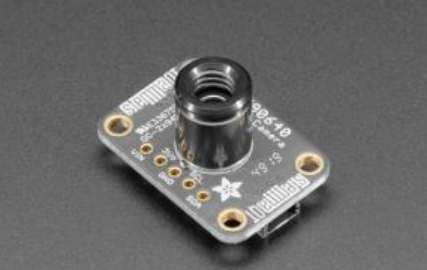
3.1 MLX90640 infrared camera module

The sensor contains a 24x32 infrared thermal sensor array. When connected to the microcontroller (or Raspberry Pi), it will return an array of 768 independent infrared temperature readings through I2C. Just like those cool thermal imagers, it is compact, simple and easy to integrate.
3.1. 1 module characteristics
This block is an infrared thermal imager module, 32 × 24 pixels, I2C interface communication, compatible with 3.3V/5V level, support Raspberry Pi
Arduino and other main controllers.
I use MLX90640 far infrared thermal sensor array, which can accurately detect target objects in specific areas and temperature ranges,
Small in size, it can be easily integrated into various industrial or intelligent control applications.
- MLX90640 far infrared thermal sensor array, 32 × 24 pixels
- It supports I2C interface communication and can be set to fast mode (the rate can reach 1MHz)
- The noise equivalent temperature difference (NETD) is only 0.1K RMS@1Hz Refresh rate, good noise performance
- The on-board level conversion circuit is compatible with the working level of 3.3V/5V
3.1. 2 relevant parameters
- Working voltage: 3.3V/5V
- Working current: < 23mA
- Communication interface: I2C (address: 0x33)
- Field angle (horizontal angle of view) × Vertical view:
- MLX90640-D55 Thermal Camera: 55° × 35 ° (small angle, suitable for remote measurement)
- MLX90640-D110 Thermal Camera: 110° × 75 ° (large angle, suitable for close measurement)
- Operating temperature: - 40 ℃ ~ 85 ℃
- Target temperature: - 40 ℃ ~ 300 ℃
- Detection accuracy: ± 1 ℃
- Refresh rate: 0.5Hz~64Hz (programmable)
- Product size: 28mm × 16 mm
- Fixing hole size: 2.0mm
3.1. 2 application scenarios
- High precision non-contact object temperature detection
- Infrared thermal imager, infrared thermometer
- Smart home, smart building, smart lighting
- Industrial temperature control, security, intrusion / movement detection
3.1. 3 interface description (taking access to MCU as an example):
- VCC: connected to 3.3V
- GND: connected to GND
- SDA: connected to MCU I2C data line
- SCL: connected to MCU I2C clock line
4 realization effect
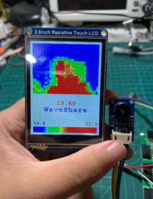
4.1 STM32+LCD image display

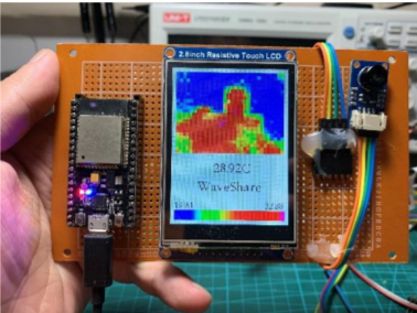
4.2 Arduino+ESP32+LCD image display

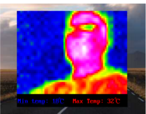
4.3 raspberry pie HDMI display

Part 5 related driver codes
#include <Adafruit_MLX90640.h>
#include "Adafruit_Arcada.h"
Adafruit_MLX90640 mlx;
Adafruit_Arcada arcada;

#if !defined(USE_TINYUSB)
  #warning "Compile with TinyUSB selected!"
#endif

File myFile;

float mlx90640To[768];   // Here we receive the float vals acquired from MLX90640

#define DE_BOUNCE 200
  // Wait this many msec between button clicks
#define MENU_LEN 12
  // Number of total available menu choices
#define MENU_ROWS 9
  // Number of menu lines that can fit on screen
#define MENU_VPOS 6
#define GRAY_33 0x528A
#define BOTTOM_DIR "MLX90640"
#define DIR_FORMAT "/dir%05d"
#define BMP_FORMAT "/frm%05d.bmp"
#define CFG_FLNAME "/config.ini"
#define MAX_SERIAL 999

// BMP File Header, little end first, Photoshop ver.
const PROGMEM uint8_t BmpPSPHead[14] = {
 0x42, 0x4D,             // "BM" in hex
 0x38, 0x09, 0x00, 0x00, // File size, 2360
 0x00, 0x00,             // reserved for app data 1
 0x00, 0x00,             // reserved for app data 2
 0x36, 0x00, 0x00, 0x00  // Offset of first pixel, 54
};

// BMP 24-bit DIB Header, little end first, Photoshop ver.
const PROGMEM uint8_t DIBHeadPSP1[40] = {
 0x28, 0x00, 0x00, 0x00,  // Header size, 40
 0x20, 0x00, 0x00, 0x00,  // pixel width, 32
 0x18, 0x00, 0x00, 0x00,  // pixel height, 24
 0x01, 0x00,              // color planes, 1
 0x18, 0x00,              // bits per pixel, 24
 0x00, 0x00, 0x00, 0x00,  // Compression method, 0==none
 0x00, 0x00, 0x00, 0x00,  // Raw bitmap data size, dummy 0
 0x12, 0x0B, 0x00, 0x00,  // Pixels per meter H, 2834
 0x12, 0x0B, 0x00, 0x00,  // Pixels per meter V, 2834
 0x00, 0x00, 0x00, 0x00,  // Colors in palette, 0==default 2^n
 0x00, 0x00, 0x00, 0x00   // Number of important colors, 0
};

// BMP file data, 2 byte padding
const PROGMEM uint8_t PSPpad[2] = {0x00, 0x00};

//Byte arrays of bitmapped icons, 16 x 12 px:
const PROGMEM uint8_t battIcon[] = {
0x0f, 0x00, 0x3f, 0xc0, 0x20, 0x40, 0x20, 0x40, 0x20, 0x40, 0x20, 0x40,
0x20, 0x40, 0x20, 0x40, 0x20, 0x40, 0x20, 0x40, 0x20, 0x40, 0x3f, 0xc0};

const PROGMEM uint8_t camIcon[] = {
0x01, 0xe0, 0x61, 0x20, 0xff, 0xf0, 0x80, 0x10, 0x86, 0x10, 0x89, 0x10,
0x90, 0x90, 0x90, 0x90, 0x89, 0x10, 0x86, 0x10, 0x80, 0x10, 0xff, 0xf0};

const PROGMEM uint8_t SDicon[] = {
0x0f, 0xe0, 0x1f, 0xe0, 0x3c, 0x60, 0x78, 0x60, 0x70, 0x60, 0x60, 0x60,
0x60, 0x60, 0x60, 0x60, 0x6f, 0x60, 0x60, 0x60, 0x7f, 0xe0, 0x7f, 0xe0};

const PROGMEM uint8_t snowIcon[] = {
0x15, 0x00, 0x4E, 0x40, 0xC4, 0x60, 0x75, 0xC0, 0x9F, 0x20, 0x0E, 0x00,
0x0E, 0x00, 0x9F, 0x20, 0x75, 0xC0, 0xC4, 0x60, 0x4E, 0x40, 0x15, 0x00};

uint8_t pixelArray[2304];   // BMP image body, 32 pixels * 24 rows * 3 bytes

// Some global values that several functions will use, including
// 5 floats to append to the BMP pixel data:
// coldest pixel, coldest color, center temp, hottest color, hottest pixel
float sneakFloats[5] = {3.1415926, 0.0, -11.7, 98.6, -12.34};      // Test values that get overwritten
uint16_t highAddr = 0, lowAddr = 0;                                // Append the pixel addresses, too

uint16_t backColor, lowPixel, highPixel, buttonRfunc = 1,
         emissivity = 95, frameRate = 4,
         thermRange = 0, paletteNum = 1, colorPal[256],            // Array for color palettes
         nextDirIndex = 0, nextBMPindex = 0, nextBMPsequence = 1;  // These keep count of SD files and dirs, 0==error
uint32_t deBounce = 0, buttonBits = 0;
boolean mirrorFlag = false, celsiusFlag = false, markersOn = true,
        screenDim = false, smoothing = false, showLastCap = false,
        save1frame = false, recordingInProg = false, buttonActive = false;
float battAverage = 0.0, colorLow = 0.0, colorHigh = 100.0;        // Values for managing color range
volatile boolean clickFlagMenu = false, clickFlagSelect = false;   // Volatiles for timer callback handling

setup()The function is executed first and only once at each startup. Its job is to initialize the system from Arcada Start with the code and the onboard hardware it will control, such as screens and buttons.

A set of tests then determines whether the flash memory is ready to receive new data BMP File.

void setup()
{
  if (!arcada.arcadaBegin()) {    // Start TFT and fill with black
    // Serial.print("Failed to begin");
    while (1);
  }
  arcada.filesysBeginMSD();       // Set up SD or QSPI flash as an external USB drive

  arcada.displayBegin();              // Activate TFT screen
  arcada.display->setRotation(1);     // wide orientation
  arcada.display->setTextWrap(false);
  arcada.setBacklight(255);           // Turn on backlight
  battAverage = arcada.readBatterySensor();

  Serial.begin(115200);
//  while(!Serial); // Wait for user to open terminal
  Serial.println("MLX90640 IR Array Example");

  if(arcada.filesysBegin()){              // Initialize flash storage, begin setting up indices for saving BMPs
    if(!arcada.exists(BOTTOM_DIR)) {      // Is base "MLX90640" directory absent?
      if(arcada.mkdir(BOTTOM_DIR))        // Can it be added?
        nextDirIndex = nextBMPindex = 1;  // Success, prepare to store numbered files & dirs
    } else {      // "MLX90640" directory exists, can we add files | directories?
      // Get the number of the next unused serial directory path
      nextDirIndex = availableFileNumber(1, BOTTOM_DIR + String(DIR_FORMAT));
      // and the next unused serial BMP name
      nextBMPindex = availableFileNumber(1, BOTTOM_DIR + String(BMP_FORMAT));
    }
  }  // By now each global index variable is either 0 (no nums available), or the next unclaimed serial num
6 finally
Technical solutions
 Design help:<Q>746876041
Complete set of single chip microcomputer projects:
https://blog.csdn.net/huawei123444/article/details/119822845