1 Introduction
Hi, everyone, this is senior Dan Cheng. Today I'd like to introduce a single chip microcomputer project to you
STM32 bus stop sign system
It can be used in curriculum design or graduation design
Technical solutions
 Design help:<Q>746876041
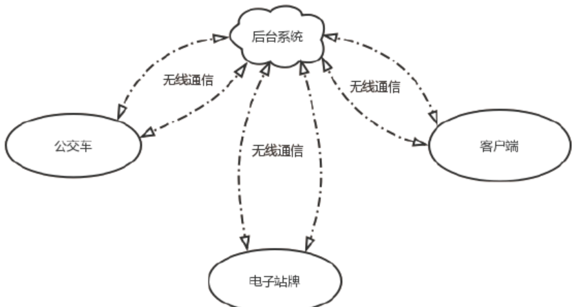
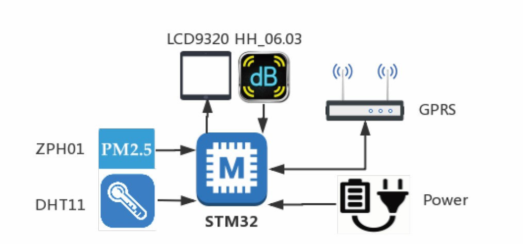
The project is mainly a real-time release system of simulated bus information, which collects bus information and releases it on the platform and mobile client. The system structure is shown in the figure below.
2 main devices
2.1 ILI9320
ILI9320 is the driving chip of LCD screen with a screen resolution of 320 × 240 pixels. The single chip microcomputer operates the screen through the FSMC bus controller. It needs 16 data lines, 6 control lines, plus 24 lines such as power grounding to drive. FSMC (Flexible Static Memory Controller) is a parallel interface of STM32. Through this interface, MCU can control NOR Flash, NAND Flash, SRAM and PSRAM. In addition to controlling memory, FSMC can also control LCD screens supporting Intel 8080 and Motorola 6800 timing.
2.2 serial GPRS module
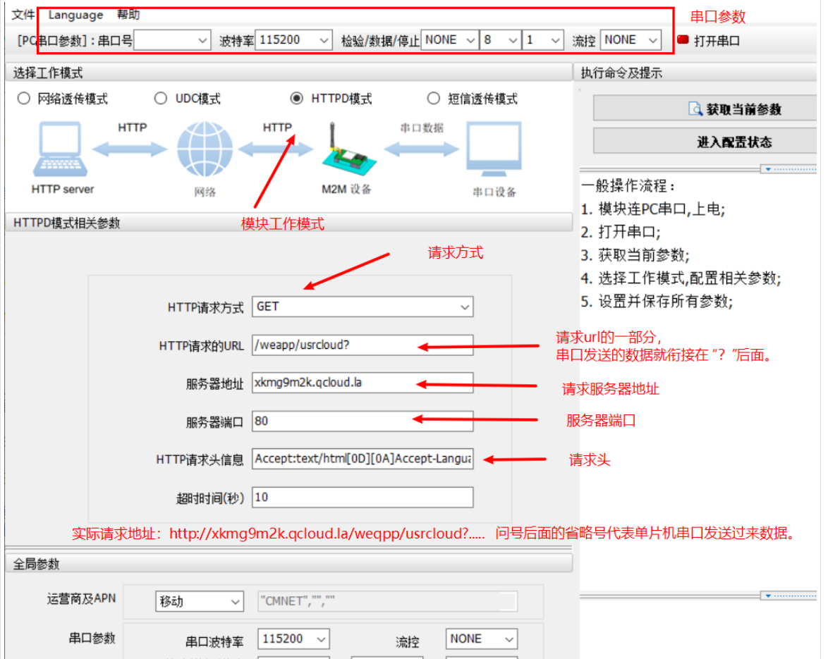
When selecting the communication module, considering the limited time, The difficulty of selecting development is relatively low (no need to develop driver) serial port GPRS module, module model: USR-GSM232-7S3, the main feature is to support GPRS network communication, support data request address customization or request to the official background, and the official background improves the API for accessing data. After the upper computer software configures the request address, it sends data to the serial port, and the module will automatically package the data and send it to the configured server address The whole module is similar to an HTTP client. Of course, the disadvantages of this module are also obvious. The 2G network speed is too slow. It takes an average of more than ten seconds to request a frame of data to receive a reply from the server.
2.3 related sensors
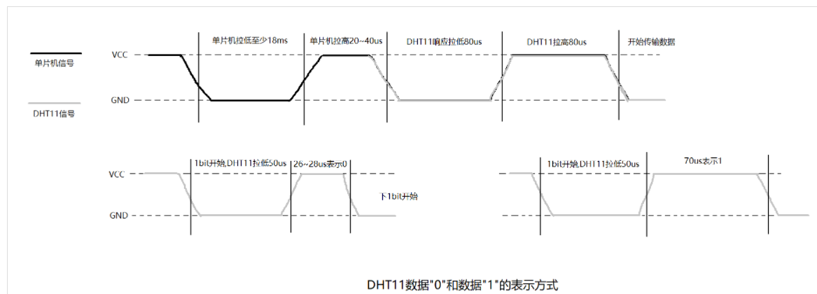
Noise sensor and PM2 5. All sensors read data through the serial port. Just initialize the serial port configuration and analyze the received data as required. The data of DHT11 temperature and humidity sensor needs to be read according to a specific sequence, and the single bus is used to transmit data between the module and the single chip microcomputer. When purchasing the module, the merchant has provided the driver code. See Github warehouse for the relevant code. The driving sequence is shown in the figure below.
3 realization effect
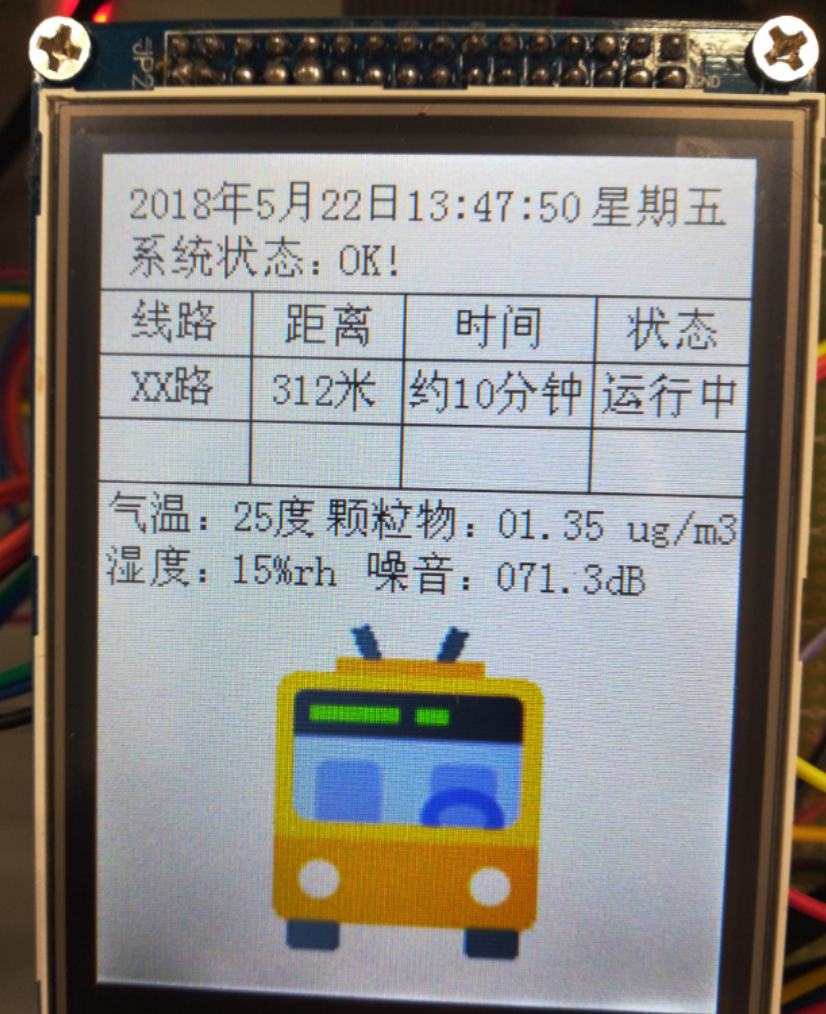
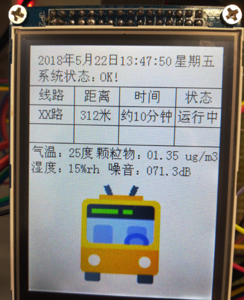
4 design principle
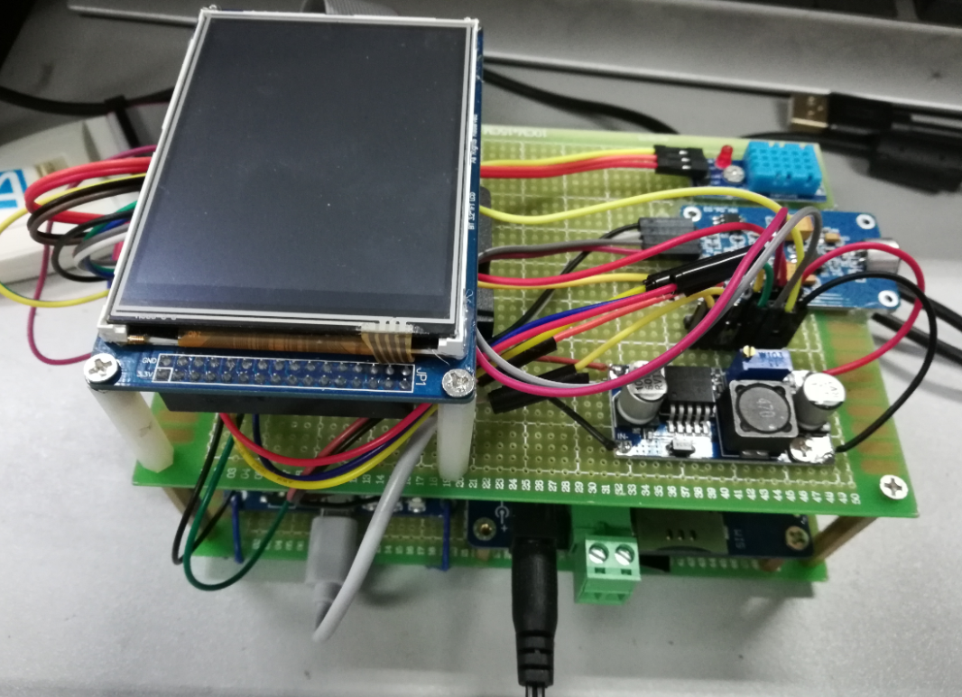
The main function of the stop board is to receive and display the bus information, but it is considered that some data can also be uploaded. Simply add several sensors to collect some data, which is about as long as below. In addition to FSMC for LCD, the communication between module and MCU is Serial UART. The whole station sign is mainly troublesome in the driver of LCD screen and the code of wireless communication.
Part 5 implementation code
ILI9320 driver code
//!  GPIO structure declaration
GPIO_InitTypeDef GPIO_InitStructure;
//!  FSMC NORSRAM structure declaration
FSMC_NORSRAMInitTypeDef  FSMC_NORSRAMInitStructure;
//!  FSMC read / write timing structure. When the mode is extended, only the read timing is valid
FSMC_NORSRAMTimingInitTypeDef  readWriteTiming;
//!  FSMC write timing structure, using extended mode
FSMC_NORSRAMTimingInitTypeDef  writeTiming;
//!  Enable FSMC clock
RCC_AHBPeriphClockCmd(RCC_AHBPeriph_FSMC,ENABLE);
//!  Enable PART B,D,E,G and AFIO multiplexing function clock,
RCC_APB2PeriphClockCmd(RCC_APB2Periph_GPIOB|RCC_APB2Periph_GPIOD|RCC_APB2Periph_GPIOE|RCC_APB2Periph_GPIOG,ENABLE);
//!  PB0 --------- backlight function
//!  PB1---------RESET function: high level operation, low level hardware reset
GPIO_InitStructure.GPIO_Pin = GPIO_Pin_0|GPIO_Pin_1;
//!  Push pull output
GPIO_InitStructure.GPIO_Mode = GPIO_Mode_Out_PP;
//!  GPIO maximum output frequency 50MHz
GPIO_InitStructure.GPIO_Speed = GPIO_Speed_50MHz;
GPIO_Init(GPIOB, &GPIO_InitStructure);

//!  PORTD multiplexed Push-Pull Outputs PD0,1,8,9,10,14,15 are data pins
//! PD4--------RD; PD5-----------WR
GPIO_InitStructure.GPIO_Pin = GPIO_Pin_0|GPIO_Pin_1|GPIO_Pin_4|GPIO_Pin_5|GPIO_Pin_8|GPIO_Pin_9|GPIO_Pin_10|GPIO_Pin_14|GPIO_Pin_15;
GPIO_InitStructure.GPIO_Mode = GPIO_Mode_AF_PP;
GPIO_InitStructure.GPIO_Speed = GPIO_Speed_50MHz;
GPIO_Init(GPIOD, &GPIO_InitStructure);

//!  Port multiplex push-pull output PE7,8,9,10,11,12,13,14,15 are data pins. See "GPIO pin and function definition. txt" file for detailed definition
GPIO_InitStructure.GPIO_Pin = GPIO_Pin_7|GPIO_Pin_8|GPIO_Pin_9|GPIO_Pin_10|GPIO_Pin_11|GPIO_Pin_12|GPIO_Pin_13|GPIO_Pin_14|GPIO_Pin_15;
//!  Multiplexed push-pull output
GPIO_InitStructure.GPIO_Mode = GPIO_Mode_AF_PP;
GPIO_InitStructure.GPIO_Speed = GPIO_Speed_50MHz;
GPIO_Init(GPIOE, &GPIO_InitStructure);

//!  PORTG multiplex push-pull output 	 PG12----CS;    PG0-----RS;
GPIO_InitStructure.GPIO_Pin = GPIO_Pin_0|GPIO_Pin_12;
//!  Multiplexed push-pull output
GPIO_InitStructure.GPIO_Mode = GPIO_Mode_AF_PP;
GPIO_InitStructure.GPIO_Speed = GPIO_Speed_50MHz;
GPIO_Init(GPIOG, &GPIO_InitStructure);

//Pull up the RESET pin to make the LCD work
GPIO_SetBits(GPIOB,GPIO_Pin_1);
6 finally
Technical solutions
 Design help:<Q>746876041
Complete set of single chip microcomputer projects:
https://blog.csdn.net/huawei123444/article/details/119822845