**
Greenhouse environment monitoring system based on 51 single chip microcomputer
Air temperature and humidity monitoring, soil temperature and humidity monitoring, light monitoring, wireless data transmission
**
The source code is attached at the end of the article
1.1 research background
With the continuous improvement of people's living standards, people pay more and more attention to their own health and have higher and higher requirements for all kinds of food. Greenhouse is used as the growth base for cultivating fruits and vegetables. Therefore, it is particularly important to monitor the growth environment of plants in Greenhouse in real time. Therefore, it is necessary to study the design of greenhouse environmental monitoring system.
1.2 design requirements
(1) Select the appropriate sensor and design the sensor signal conditioning circuit;
(2) LCD 12864 is used to display the greenhouse environmental parameters in real time;
(3) The design of key circuit can set the upper and lower limits of environmental parameters;
(4) An audible and visual alarm circuit is set, and the threshold is set by pressing the key to alarm after exceeding the limit;
(5) Realize wireless transmission through NRF24L01 module;
(6) The screen displays the real-time time and can be adjusted;
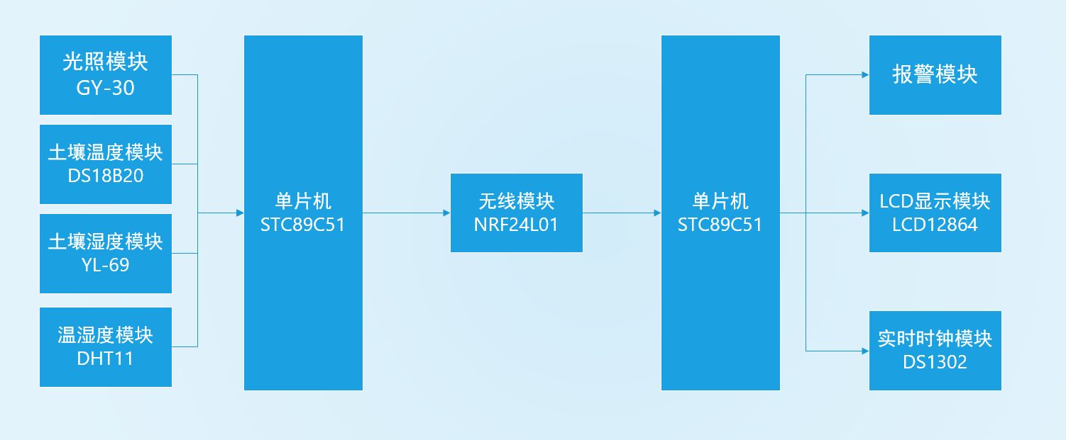
2.1 system scheme block diagram

2.2 scheme analysis
The transmitting board of the environmental monitoring system is composed of GY-30 lighting module, DS18B20 soil temperature module, YL-69 soil humidity module, DHT11 temperature and humidity module and STC89C52 single chip microcomputer as the control core to realize the collection of on-site lighting, soil temperature and humidity and air temperature and humidity data.
Taking DS1302 real-time clock module, LCD12864 display module, buzzer alarm module and STC89C52 single chip microcomputer as the control core, the receiving board of the environmental monitoring system is composed to realize the collection of real-time data and the display of the received data of the transmitting board, as well as the audible and visual alarm after exceeding the limit.
The data communication between the transmitting board and the receiving board is realized through the NRF24L01 wireless module.
1. Single chip microcomputer selection
The single chip microcomputer adopts the single chip microcomputer STC89C52 of macro crystal technology. STC89C52 is a low-power, high-performance CMOS 8-bit microcontroller. STC89C52 uses the classic MCS-51 kernel, with a smart 8-bit CPU and in system programmable Flash.
2. Lighting module circuit
GY-30 is used to form the lighting module circuit. GY-30 is a digital light intensity module with built-in ROHM-BH1750FLV chip. The chip has a built-in 16bitAD converter, which can be directly digital output, and the measurement light intensity range is 0-65535lx (accuracy optional). In addition, the module has built-in level conversion, supports 3-5V power supply, and can be directly connected with 5V MCU IO; Provide IIC interface for external use.

3. Soil temperature module circuit
DS18B20 is used to form the soil temperature module circuit. DS18B20 is a commonly used digital temperature sensor. Its output is digital signal. It has the characteristics of small volume, low hardware overhead, strong anti-interference ability and high precision. The utility model has the advantages of convenient wiring and can be applied to a variety of occasions after being packaged.

4. Soil moisture module circuit
The soil moisture module circuit adopts YL-69. YL-69 is a simple soil humidity sensor. It is a capacitive sensor. It mainly uses humidity sensitive capacitance. When the humidity of the environment changes, the medium in the environment where the humidity sensitive capacitance exists will change, resulting in the change of the capacitance value in the humidity sensitive capacitance, which is directly proportional to the humidity value. Because of its high sensitivity, fast response speed, small hysteresis, small volume and very low power consumption, the humidity sensitive capacitor is easy to miniaturize and integrate. YL-69 adopts CMOS technology, which can ensure its low power consumption and high reliability and stability. The sensor contains a capacitive polymer humidity sensitive element and a temperature sensor made of energy gap material, which are connected with A/D converter and serial interface circuit on the same chip.

5. Air temperature and humidity module circuit
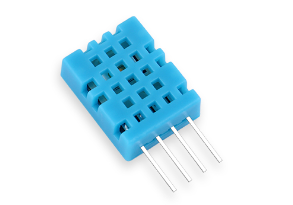
The air temperature and humidity module circuit adopts DHT11 module. DHT11 digital temperature and humidity sensor is a temperature and humidity composite sensor with calibrated digital signal output. It applies special digital module acquisition technology and temperature and humidity sensing technology to ensure that the product has high reliability and excellent long-term stability. The sensor includes a resistive humidity sensing element and an NTC temperature measuring element, and is connected with a high-performance 8-bit single chip microcomputer. Therefore, the product has the advantages of excellent quality, ultra fast response, strong anti-interference ability and high cost performance.

6. Wireless module circuit
The wireless module circuit adopts nRF24L01 module. NRF24L01 is a new monolithic RF transceiver, which works in the 2.4 GHz ~ 2.5 GHz ISM band. Built in frequency synthesizer, power amplifier, crystal oscillator, modulator and other functional modules, and integrated with enhanced ShockBurst technology, in which the output power and communication channel can be configured by program.

7.LCD12864 display module circuit
128X64 with Chinese font is a dot matrix graphic LCD display module with 4-bit / 8-bit parallel, 2-wire or 3-wire serial interfaces, and contains national standard level-1 and level-2 simplified Chinese font; Its display resolution is 128 × 64. Built in 8192 1616 point Chinese characters and 128 168 point ASCII character sets Using the flexible interface mode and simple and convenient operation instructions of the module, a full Chinese human-computer interaction graphical interface can be formed.

8. Alarm module circuit
The alarm circuit of this design is realized by an electromagnetic active buzzer. The alarm circuit is connected to a specific pin of the single chip microcomputer and will control the operation of the alarm circuit according to the output signal at any time. Set a temperature limit. When the collected temperature exceeds the limit, the buzzer will ring all the time; When the temperature is within the temperature limit, the buzzer stops ringing.
9. Real time clock module circuit
DS1302 is a real-time clock circuit with high performance, low power consumption and ram launched by DALLAS company in the United States. It can time the year, month, day, week, hour, minute and second. It has leap year compensation function, and the working voltage is 2.0V~5.5V. Three wire interface is used for synchronous communication with CPU, and burst mode can be used to transmit multiple bytes of clock signal or RAM data at one time.

4.1 main program design
The whole software part is divided into the collection of air temperature and humidity, soil temperature and humidity and light data of transmitting board, wireless transmission of data and display of data of receiving board.
Firstly, DHT11 initializes, collects air humidity information, temperature information and return data by calling the collection data function, and then stores the collected data in the transmission buffer through internal AD conversion;
Initialize the module through YL-69 initialization function, and then call the acquisition data function to read the probe humidity information of the current sensor, which is the current probe capacitance value. Collect the soil humidity information. Because the module has no AD conversion circuit, it is externally connected with ADC0832 chip. Initialize ADC0832 chip, perform ad conversion, return data, and then store the data in the transmission buffer;
Through the working mode of DS18B20 initialization function initialization module, call the function of collecting soil temperature information, internally adopt the principle of subtraction counter, finally get the current temperature data, return the data, and store the data serially in the transmission buffer;
Initialize the working mode through GY-30 initialization function, call and collect the function of lighting information, the collected information is divided into 8 bits, and take out the data bit by bit, respectively × The final data is obtained by multiplying the corresponding position, the data is returned, and the obtained data is stored in the transmission buffer;
Finally, by setting the initialization of nRF24L01, the array of the transmission buffer is sent to the data transmission function of nRF24L01. NRF24L01 sends the data in the transmission buffer to the receiving board and to the receiving MCU according to the data length in the corresponding buffer.
Put the above modular program into the while loop, so as to realize the real-time collection and real-time transmission of data. The basic requirements of this course design are realized. The following figure is the main program block diagram of the sending board:

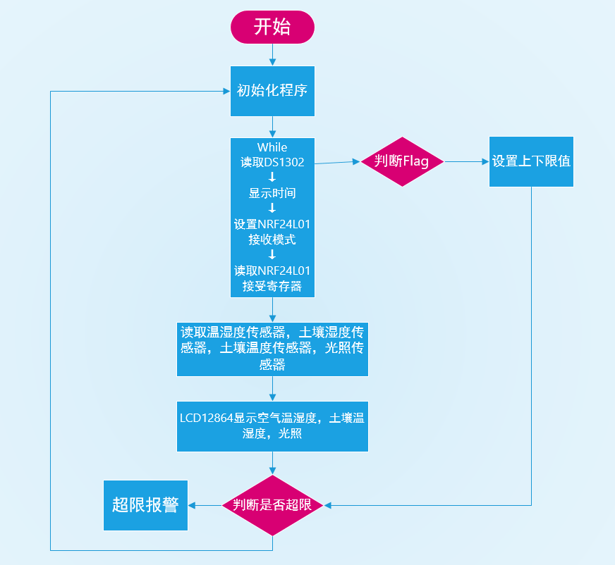
The data receiving board receives the data through the wireless module, stores the data of the transmission buffer in the reception buffer, and then reads the value of the corresponding index by displaying the corresponding position data in the reception buffer.
Call 12864 display function to digitally display the value. After receiving the data of time, minute and second pins corresponding to DS1302 real-time clock chip, call the display function of corresponding date and corresponding real-time transmitted data through program control carry;
Define the key at the corresponding position in the program, sbit define the key corresponding to the pin of the MCU, and set the function of the key from S1-S5. The corresponding functions are: time setting, threshold setting, counting up, counting down and confirmation.
Press time setting to set the second of time. When you press it again, the corresponding cursor can be divided into minute position, and then press it again to enter the position, and so on;
Press the threshold setting button to enter the air temperature, humidity setting, light setting, soil temperature and soil humidity threshold setting respectively, so as to set the corresponding data.
Press S5, the last key, to confirm the set current time and threshold; After that, the program enters to monitor the current real-time data of temperature, air humidity, soil temperature and soil humidity exceeding the threshold. If the threshold is exceeded, the buzzer will give an alarm. Otherwise, the flag will be judged as 0 and continue to execute.
Put the above program into a large cycle, so as to realize the function of real-time acquisition of data sent by the transmitting board. The following figure is the program design diagram of the receiving board:

Some physical drawings, PCB display


If you need physical pcb board, please send a private letter
Part of the program source code
Part of the source code is written in keil4
// Emitter board source code:
#include <stc89c52.h>
#include <intrins.h>
typedef unsigned char uchar;
typedef unsigned int uint;
#define FOSC 11059200L      //System frequency
#define BAUD 2400           //UART baudrate
unsigned char flagcom=0;
//2401IO port definition sbit 	 MISO 	= P0^2;
sbit 	MOSI	=P0^4;
sbit	SCK	    =P0^1;
sbit	CE	    =P0^0;
sbit	CSN		=P0^5;
sbit	IRQ		=P0^3;
unsigned char xdata TxBuf[32]=0;		//2401 transmit register
sbit     DQ=P2^7;        //DHT11
//bh1750
sbit	  SCL=P2^1;      //IIC clock pin definition
sbit  	  SDA=P2^2;      //IIC data pin definition
#define 	   Slaveaddress 0x46 / / defines the slave address of the device in the IIC bus. It can be modified according to the ALT address pin
                              //The address of ALT address pin is 0x46 when grounded and 0x3A when connected to power supply
typedef   unsigned char BYTE;
typedef   unsigned short WORD;
uchar   BUF[8];                         //Receive data buffer
unsigned char  xdata    ge,shi,bai,qian,wan;            //Display variables
uchar tem;  //temperature
uchar  hum;  //humidity
uint guangzhao=0;		//illumination
uint pm25=0;			//pm2.5
uint tw=0;  //soil temperature
uint ts=0;  //soil moisture
uint flag1=0;
sbit 	LED1=P1^1;
sbit 	LED2=P1^4;
//*************************************ADC0832 definition*****************/
//ADC0832
sbit CS = P1^5;
sbit CLK = P1^6;
sbit DIO = P1^7;
//*********************************************NRF24L01*************************************
#define TX_ADR_WIDTH    5   	// 5 uints TX address width
#define RX_ADR_WIDTH    5   	// 5 uints RX address width
#define TX_PLOAD_WIDTH  32  	// 20 uints TX payload
#define RX_PLOAD_WIDTH  32  	// 20 uints TX payload
uchar const TX_ADDRESS[TX_ADR_WIDTH]= {0x34,0x43,0x10,0x10,0x01};	//Local address
uchar const RX_ADDRESS[RX_ADR_WIDTH]= {0x34,0x43,0x10,0x10,0x01};	//Receiving address
//***************************************NRF24L01 Register instruction*******************************************************
#define READ_REG        0x00  	// Read register instruction
#define WRITE_REG       0x20 	// Write register instruction
#define RD_RX_PLOAD     0x61  	// Read receive data instruction
#define WR_TX_PLOAD     0xA0  	// Write pending data instruction
#Delay Functions
void inerDelay_us(unsigned char n)
{
	for(;n>0;n--)
		_nop_();
}
void Delay5ms()
{
    WORD n = 560;
    while (n--);
}
void delay_nms(unsigned int k)
{
unsigned int i,j;
for(i=0;i<k;i++)
{
for(j=0;j<121;j++)
{;}}
}
void Delay5us()
{
    _nop_();_nop_();_nop_();_nop_();
    _nop_();_nop_();_nop_();_nop_();
	_nop_();_nop_();_nop_();_nop_();
	_nop_();_nop_();_nop_();_nop_();
}
//******************************Reset ds18b20************/
void Init_ds18b20(void) {
	DQ = 1;
	delay(1);
	DQ = 0;
	delay(250);
	DQ = 1;
	delay(100);
}

#NRF24L01 initialization
void init_NRF24L01(void)
{
    inerDelay_us(100);
 	CE=0;    // chip enable
 	CSN=1;   // Spi disable
 	SCK=0;   // Spi clock line init high
	SPI_Write_Buf(WRITE_REG + TX_ADDR, TX_ADDRESS, TX_ADR_WIDTH);    // Write local address
	SPI_Write_Buf(WRITE_REG + RX_ADDR_P0, RX_ADDRESS, RX_ADR_WIDTH); // Write receiver address
	SPI_RW_Reg(WRITE_REG + EN_AA, 0x01);      //  Channel 0 Auto 	 ACK reply allowed
	SPI_RW_Reg(WRITE_REG + EN_RXADDR, 0x01);  //  Only channel 0 is allowed as the receiving address. If multiple channels are required, please refer to Page21
	SPI_RW_Reg(WRITE_REG + RF_CH, 0);        //   Set the working channel to 2.4GHZ, and the transceiver must be consistent
	SPI_RW_Reg(WRITE_REG + RX_PW_P0, RX_PLOAD_WIDTH); //Set the received data length to 32 bytes this time
	SPI_RW_Reg(WRITE_REG + RF_SETUP, 0x07);   		//Set the transmission rate to 1MHZ and the maximum transmission power to 0dB
	SPI_RW_Reg(WRITE_REG + CONFIG, 0x0e);   		 // IRQ transceiver completion interrupt response, 16 bit CRC, main transmitter

}