According to the halcon routine Moments_Object_Model_3D
You can set "lut", "color_attrib" and other parameters to make the point cloud display the color in ColorSpace according to the scale in a certain direction
* Set visualization parameters for the 3d object model
* A lookup table (lut) is set that transforms attribute values into
* a color. In this example the color encodes the value of the
* z-component of the data. The alpha parameter defines the
* transparency of the object model.
GenParamName := ['lut','color_attrib','light_position','disp_pose','alpha']
GenParamValue := ['color1','coord_z','0.0 0.0 -0.3 1.0','true',0.9]
Similarly, you can use
xyz_attrib_to_object_model_3d
This operator adds the brightness map into the 3D model when generating the point cloud
xyz_attrib_to_object_model_3d (X, Y, Z, ImageRGB, ['&red', '&green', '&blue'], ObjectModel3D)
prepare_object_model_3d (ObjectModel3D, 'segmentation', 'true', [], [])
visualize_object_model_3d (WindowHandle, ObjectModel3D, [], [], ['red_channel_attrib', 'green_channel_attrib', 'blue_channel_attrib'], ['&red', '&green', '&blue'], [], [], [], PoseOut)
The generated Object 3D contains a single channel gray image
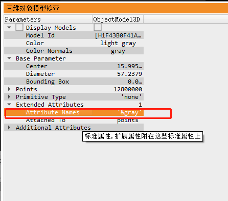
You can display the luminance map through the Intensity parameter
GenParamName := ['light_position','disp_pose','alpha','intensity','point_size']
GenParamValue := ['0.0 0.0 -0.3 1.0','true',0.9,'&gray',1]
sample_object_model_3d (ObjectModel3D, 'fast', 0.05, [], [], SampledObjectModel3D)
visualize_object_model_3d (WindowHandle, SampledObjectModel3D, [], [], GenParamName, GenParamValue, [], [], [], PoseOut)
There is a slight difference in. NET because xyz_attrib_to_object_model_3d this is a halcon function, not an operator;
After a careful look at this function, I found that many previous statements were fool proof. The more important statements are:
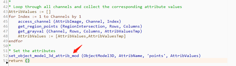
So the code in NET is
                PCObjectModel3D.XyzToObjectModel3d(X,Y,DeepImage);
                //Shading with luminance maps
                HRegion DomainRegion = IntensityImage.GetDomain();
                HTuple Rows, Cols;
                DomainRegion.GetRegionPoints(out Rows,out Cols);
                double[] val =  IntensityImage.GetGrayval(Rows, Cols);
                PCObjectModel3D.SetObjectModel3dAttribMod("&gray","points", val);
                InfoWindow.ShowMessage("Brightness map coloring completed");
According to the above steps:
Generate a point cloud and render the color display according to the Z direction

If you need to paste the brightness diagram for display, you can add the pair of parameters' intensity '-' & Gray 'to the display parameters (the detailed code has been pasted above)
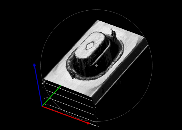
According to the above comparison, the height difference can be well seen according to the coloring in Z direction, but the lines on the product surface can not be seen clearly;
If the map is a brightness map, you can well see the reflection on the product surface, but the height is not obvious and intuitive;
According to the halcon code provided by Keyence, there is a compromise:
*Convert the height information of the product into the H-channel tone in the HSV color channel
*Manually create a single channel graph as the saturation channel S channel
*The luminance map is used as the lightness Channel V channel
*Convert HSV picture into RGB picture and add RGB three channels to the model respectively
           double min_Color = 255;
            double max_Color = 0;
            double gray_mix_percent = 0.7;

            double DeepMin = 0;
            double DeepMax = 30;

            double Convert_K = (max_Color - min_Color) / (DeepMax - DeepMin);
            double Convert_B = min_Color - Convert_K * DeepMin;

            HImage HSV_H = DeepImage.ScaleImage(Convert_K, Convert_B);
            HSV_H = HSV_H.ConvertImageType("byte");
            //HSV_H.WriteImage("tiff",0,"D:\\TImage.tiff");

            //HRegion ZeroRegion = IntensityImage.Threshold(0.0, 0.0);
            //HRegion FullRegion = IntensityImage.GetDomain();
            //HRegion ResultRegion = FullRegion.Difference(ZeroRegion);

            //HImage IntensityBlobImage = IntensityImage.ReduceDomain(ResultRegion);
            HImage HSV_V = IntensityImage.ScaleImage(gray_mix_percent, 255 * (1 - gray_mix_percent));
            //HSV_V.WriteImage("tiff", 0, "D:\\TImageIntensity.tiff");

            int Imagewidth, imageheight;
            IntensityImage.GetImageSize(out Imagewidth,out imageheight);

            double Saturation = (1 - gray_mix_percent) * 512;
            HImage HSV_S = new HImage();
            HSV_S.GenImageSurfaceFirstOrder("byte",0,0, Saturation,0,0, Imagewidth, imageheight);

            HImage ChannelRed =  HSV_H.TransToRgb(HSV_S,HSV_V,out HImage ChannelGreen,out HImage ChannelBlue,"hsv");
            RainBowImage =  ChannelRed.Compose3(ChannelGreen, ChannelBlue);
                //Use rainbow coloring
                HImage Cred =  RainBowImage.AccessChannel(1);
                HRegion DomainRegion = Cred.GetDomain();
                HTuple Rows, Cols;
                DomainRegion.GetRegionPoints(out Rows, out Cols);
                double[] val = Cred.GetGrayval(Rows, Cols);
                PCObjectModel3D.SetObjectModel3dAttribMod("&red", "points", val);

                HImage Cgreen = RainBowImage.AccessChannel(2);
                val = Cgreen.GetGrayval(Rows, Cols);
                PCObjectModel3D.SetObjectModel3dAttribMod("&green", "points", val);

                HImage Cblue = RainBowImage.AccessChannel(3);
                val = Cblue.GetGrayval(Rows, Cols);
                PCObjectModel3D.SetObjectModel3dAttribMod("&blue", "points", val);
                InfoWindow.ShowMessage("Rainbow coloring complete");
                //Rainbow shading
                HTuple paraname = new HTuple( "disp_pose", "alpha", "point_size", "disp_normals", "red_channel_attrib", "green_channel_attrib", "blue_channel_attrib");
                HTuple paraValue = new HTuple("true", 1, 1, "false","&red", "&green", "&blue");

Rainbow effect, adjust the saturation channel to show more lightness channel or more hue channel.