Topic 1: what are the reasons why the video between the headquarters and branches has flower screens and the voice images are not synchronized?
Insufficient bandwidth, more packet loss, network jitter and high delay.
Question 2: how to deploy QoS (only write out the device name when deploying on that device) (1 point how to deploy QoS needs to specify the detailed configuration parameter information. (3 points)
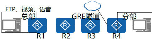
R1 and R4 serve as the service provider edge equipment PE on the headquarters side and branch side respectively, and establish GRE tunnels across the equipment to realize the interworking between the headquarters and the distributed private network. R2 and R3 represent backbone devices P in the service provider network, It is not necessary to configure QoS on P (R2 and R3) devices, because after GRE encapsulates the message, the QoS information in the ip packet header of the inner layer (enterprise intranet) message will be copied to the outer layer (service provider network) the QoS location of the ip packet header of the message to ensure that the equipment and network along the way can correctly process the superior QoS information. It is impossible to deploy on all end-to-end devices, because the actual number of service provider network backbone devices P is huge and the configuration workload is heavy, and the operator does not allow it.
1) Use complex stream classification in the incoming direction of R1, and configure MQC to mark voice, video and FTP service queues. (take voice EF, video AF41 and FTP AF31 as examples)
	    acl 3002
		  rule 5 permit ip source Voice address wildcard
		acl 3003
			rule 5 permit ip source Video address wildcard
		acl 3004
			rule 5 permit ip source FTP Address wildcard
		traffic classifier C1
			if-match acl 3002
 		traffic classifier C2
			if-match acl 3003
 		traffic classifier C4
			if-match acl 3004
		traffic behavior b1
			remark dscp ef
		traffic behavior b1
			remark dscp af41
		traffic behavior b1
		    remark dscp af31
		traffic policy p1
			classifier C1 behavior b1
			classifier C2 behavior b2
			classifier C3 behavior b3
		interface <Interface number>
		 	traffic-policy p1 inbound
2) Configure MQC in the R1 outgoing direction, use simple stream classification to allocate sufficient bandwidth for voice and video services, and solve the problem of synchronization between flower screen and voice (note that the bandwidth should be reasonably allocated according to the actual traffic size of the service to ensure QoS effect. Below, take voice 50%, video 40%, FTP 30%)
traffic classifier voice
	if-match dscp ef
traffic classifier video
	if-match dscp af41
traffic classifier data
	if-match dscp af31
traffic behavior voice
	queue ef bandwidth pct 50
traffic behavior video
	queue af41 bandwidth pct 40
traffic behavior data
	queue af31 bandwidth pct 10
traffic policy p2
 	classifier voice behavior voice
 	classifier video behavior vido
 	classifier data behavior data
interface tunnel 0/0/1
	traffic-policy p2 outbound
3) Configure MQC in R4 outgoing direction, use simple stream classification to ensure sufficient bandwidth for voice and video services, and solve the non synchronization between flower screen and voice.
traffic classifier voice
	if-match dscp ef
traffic classifier video
	if-match dscp af41
traffic classifier data
	if-match dscp af31
traffic behavior voice
	remark ef bandwidth pct 50
traffic  behavior video
	remark dscp af41 bandwidth pct 40
traffic behavior data
	remark dscp af31 bandwidth pct 5
traffic policy p3
classifier voice behavior voice
classifier video behavior video
classifier data behavior data
interface <Interface number>
	traffic-policy p3 outbound
The above is the QoS configuration from R1 to R4. It is also necessary to configure the QoS traffic configuration from R4 to R1 in the opposite direction. The configuration method is similar and will not be repeated.
Topic 3: the branch now accesses the external network. The bandwidth used under normal circumstances is 100M, and the bandwidth guaranteed under link congestion is 50M. How to implement it and explain the specific reasons) (4 points)
Scheme: speed limit and CBQ are used. Configure traffic shaping or traffic supervision under the external network interface view of R4 to realize the loan speed limit of 100M. The reference configuration is as follows:
qos gts cir 1024000                                #Shaping the outlet flow of the interface
qos car inbound/outbound cir 1024000  #Supervise the inlet / outlet flow of the interface
Through the MQC command line of CBQ, classify the traffic (generally use ACL to match the traffic), allocate the partial traffic to the queue AF in the traffic behavior, allocate 50M bandwidth (queue af bandwidth 51200) to the AF queue, associate the flow classification and popularity in the traffic policy, and apply it in the outbound direction of the extranet interface.
Characteristics of AF queue: each AF queue corresponds to a type of message, and the user can set the bandwidth occupied by each type of message. When the system schedules the message out of the queue, it sends the message out of the queue according to the bandwidth set by the user for various messages, which can realize the fair scheduling of various types of queues. When the interface has remaining bandwidth, AF shares the remaining bandwidth according to the weight.