1, HDLC principle and configuration
1. HDLC principle
HDLC (high level data link control) advanced data link control protocol, which is an IOS standard data link control protocol and a bit oriented link layer protocol. The protocols in the standard HDLC protocol family run and synchronize on the serial line.
1.1.1 HDLC frame structure
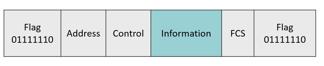
Flag: all information transmission must start with a flag character and end with the same character. This flag character is 01111110, which is called flag field (F). A complete information unit is formed from the start flag to the end flag, which is called a frame. All information is transmitted in the form of frames, and the flag character provides the boundary of each frame. The receiver can find the beginning and end of the frame by searching "01111110", so as to establish frame synchronization.
Address and control: after the flag field, there can be an address A(Address) and a control C(Control). The address is used to specify the address of the secondary station communicating with it. Control can specify several commands. SDLC specifies that the width of address and control is 8 bits. HDLC allows address to be any length and control to be 8 bits or 16 bits. The receiver must check the first bit of each address byte. If it is "0", it will be followed by another address byte; If "1", this byte is the last address byte. Similarly, if the first bit of the first control byte is "0", there is a second control byte, otherwise there is only one byte.
Information: following Control is the information field. Information contains the data to be transmitted. Not every frame must have information. That is, information can be 0. When it is 0, this frame is mainly a Control command.
FCS: immediately following the Information is the two byte frame check. The frame check is called FC(Frame Check), and the check sequence is FCS(Frame check Sequence). Both SDLC and HDLC adopt 16 bit cyclic redundancy code CRC (Cyclic Redundancy Code), and its generated polynomial is CCITT polynomial X16+X12+X^5+1. Except for the flag and the automatically inserted "0" bit, all Information participates in CRC calculation. CRC encoder adds redundant supervision code bits to each code group when sending code groups. When receiving, the decoder can correct the error code within the error correction range and check the error code within the error correction range, but it cannot correct it. Multi bit errors beyond the scope of correction and correction will not be detected by verification.
1.1.2 HDLC frame type
- Information frame (I frame): information frame is used to transmit effective information or data, usually referred to as I frame. The I frame is marked with the first bit of the control word as "0". The N(S) in the control field of the information frame is used to store the serial number of the transmission frame, so that the sender does not have to wait for confirmation to send multiple frames continuously. N ® It is used to store the sequence number of the next expected frame to be received by the receiver, n ®= 5 means that the receiver will receive frame 5 in the next frame, in other words, the frames before frame 5 are received. N(S) and n ® All are 3-bit binary codes, which can be taken as 0 ~ 7.
- Monitoring frame (s frame): monitoring frame is used for error control and flow control, usually referred to as s frame. S frame is marked by "10" in the first and second bits of the control field. S frame has information field, only 6 bytes, i.e. 48 bits. The third and fourth bits of the control field of S frame are s frame type codes, which are represented by four different codes (as follows). It can be seen that receiving ready RR s frames and receiving not ready RNR s frames have two main functions: first, these two types of s frames are used to indicate that the slave station is ready or not ready to receive information; Secondly, all received I frames with a number less than N(R) are confirmed. Reject REJ and select reject SREJ type s frames to indicate to the opposite station that an error has occurred. The REJ frame is used in the GO-back-N strategy to request retransmission. The frame before N(R) has been confirmed. When an I frame with N(S) equal to N(R) of the REJ type s frame is received, the REJ state can be cleared. SREJ frame is used to select the retransmission strategy. When N(S) of an N(S) and other SREJ frame is received ® The SREJ state should be eliminated when the I frame of the.
00 - receive ready (RR), sent by master station or slave station. The master station can use the RR type S frame to poll the slave station, that is, it wants the transmission number of the slave station to be N ® If there is such a frame, it will be transmitted; The slave station can also respond with RR type S frame, indicating that the number of the next I frame that the slave station wants to receive from the master station is N ®.
01 - reject (REJ), which is sent by the master station or slave station to require the sender to number the slave N ® The first frame and all subsequent frames are retransmitted, which also implies N ® The previous I frame has been received correctly.
10 - reception not ready (RNR), indicating that the number is less than N ® The I frame of has been received, but it is currently busy and not ready to receive. The number is N ® I frame, which can be used to control link traffic.
11 - select reject (SREJ), which requires the sender to send the number N ® A single I-frame and implies that all its numbered I-frames have been confirmed.
- Unnumbered frame (U frame): unnumbered frame is named because its control field does not contain numbers N(S) and N(R), which is referred to as U frame for short. U frame is used to provide link establishment, removal and various control functions. These control functions are defined by 5 m bits (M1, M2, M3, M4, M5, also known as correction bits). Five m bits can define 32 additional command functions or 32 reply functions, but many are vacant at present.
1.2 two key technologies
1.2.1 "0" bit insertion / deletion Technology
SDLC/HDLC protocol specifies 01111110 as the flag byte, but there may be characters of the same mode in the information. In order to distinguish it from the flag, the "0" bit insertion and deletion technology is adopted. The specific method is that when the sender sends all information (except flag bytes), as long as it encounters 5 consecutive "1", it will automatically insert a "0". When the receiver receives data (except flag bytes), if it receives 5 consecutive "1", it will automatically delete the subsequent "0" to restore the original form of the information. This "0" bit insertion and deletion process is automatically completed by hardware, which is easier to implement than the above character oriented "data transparency".
1.2.2 abnormal end of SDLC / HDLC
If an error occurs during transmission, the SDLC/HDLC protocol invalidates the frame with an abort character, or failure sequence. In HDLC procedure, 7 consecutive "1" are regarded as invalid characters, while in SDLC, the invalid characters are 8 consecutive "1". Of course, the "0" bit insertion / deletion technique is not used in the failure sequence. SDLC/HDLC protocol stipulates that no data interval is allowed within one frame. Between two frames of information, the transmitter can continuously output a sequence of flag characters or a continuous high level, which is called idle signal.
1.3 response mode of HDLC
1.3.1 normal response mode NRM
Normal response mode (NRM) is an unbalanced data link operation mode, sometimes also known as unbalanced normal response mode. This operation mode is applicable to terminal oriented point-to-point or one point and multipoint links. In this operation mode, the transmission process is started by the master station. The slave station can transmit information to the master station as a response only after receiving a command frame from the master station. The response information can be composed of one or more frames. If the information is composed of multiple frames, it should be pointed out which is the last frame. The master station is responsible for managing the whole link, and has the right to poll, select the slave station and send commands to the slave station. At the same time, it is also responsible for controlling timeout, retransmission and various recovery operations.
1.3.2 asynchronous balance mode ABM
Asynchronous balanced mode (ABM) is an operation mode that allows any node to start transmission. In order to improve the link transmission efficiency, nodes need a higher amount of information transmission in both directions. Under this operation mode, any station can start transmission operation at any time. Each station can be used as both master station and slave station. Each station is a combined station. Each station has the same set of protocols. Any station can send or receive commands or give responses, and each station has the same responsibility for the error recovery process.
1.3.3 asynchronous response mode
Asynchronous response mode (ARM) is also an unbalanced data link operation mode. Different from NRM, the transmission process under arm is started by the slave station. One or a group of frames actively sent from the slave station to the master station may contain information or may be frames sent only for the purpose of control. In this operation mode, the timeout and retransmission are controlled by the slave station. This method is essential for multi station Lianlu with polling mode.
2.1 HDLC configuration method
2.1DHLC basic configuration
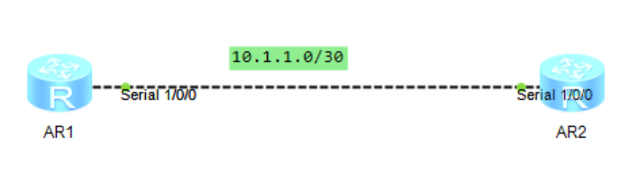
Topology:
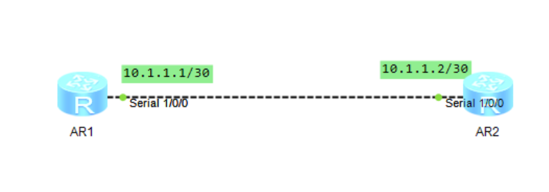
AR1:
<Huawei>system-view
[Huawei]interface Serial 1/0/0
[Huawei-Serial1/0/0]ip address 10.1.1.1 30
[Huawei-Serial1/0/0]link-protocol hdlc
[Huawei-Serial1/0/0]quit
The same is true for AR2 configuration.
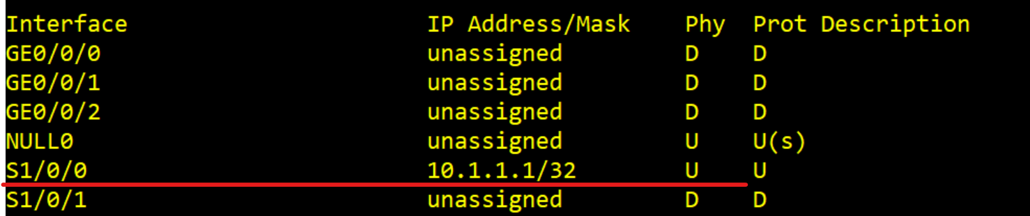
2.2 IP address borrowing configuration
Experimental topology:
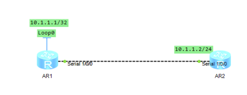
AR1:
<Huawei>system-view[Huawei]interface LoopBack 0
[Huawei-LoopBack0]ip address 10.1.1.1 32
[Huawei-LoopBack0]quit
[Huawei]interface Serial 1/0/0
[Huawei-Serial1/0/0]link-protocol hdlc
[Huawei-Serial1/0/0]ip add unnumbered interface  LoopBack 0
[Huawei-Serial1/0/0]quit
[Huawei]ip route-static 10.1.1.0 24 Serial 1/0/0
2, PPP principle and configuration
PPP(Point-to-Point Protocol) provides a standard method for transmitting multi protocol data packets on point-to-point link. PPP is character oriented and is a widely used point-to-point communication protocol in data link layer. Like HDLC protocol, it works as data link layer.
2.1 PPP principle
2.1.1 frame structure
| field | length | meaning |
|---|---|---|
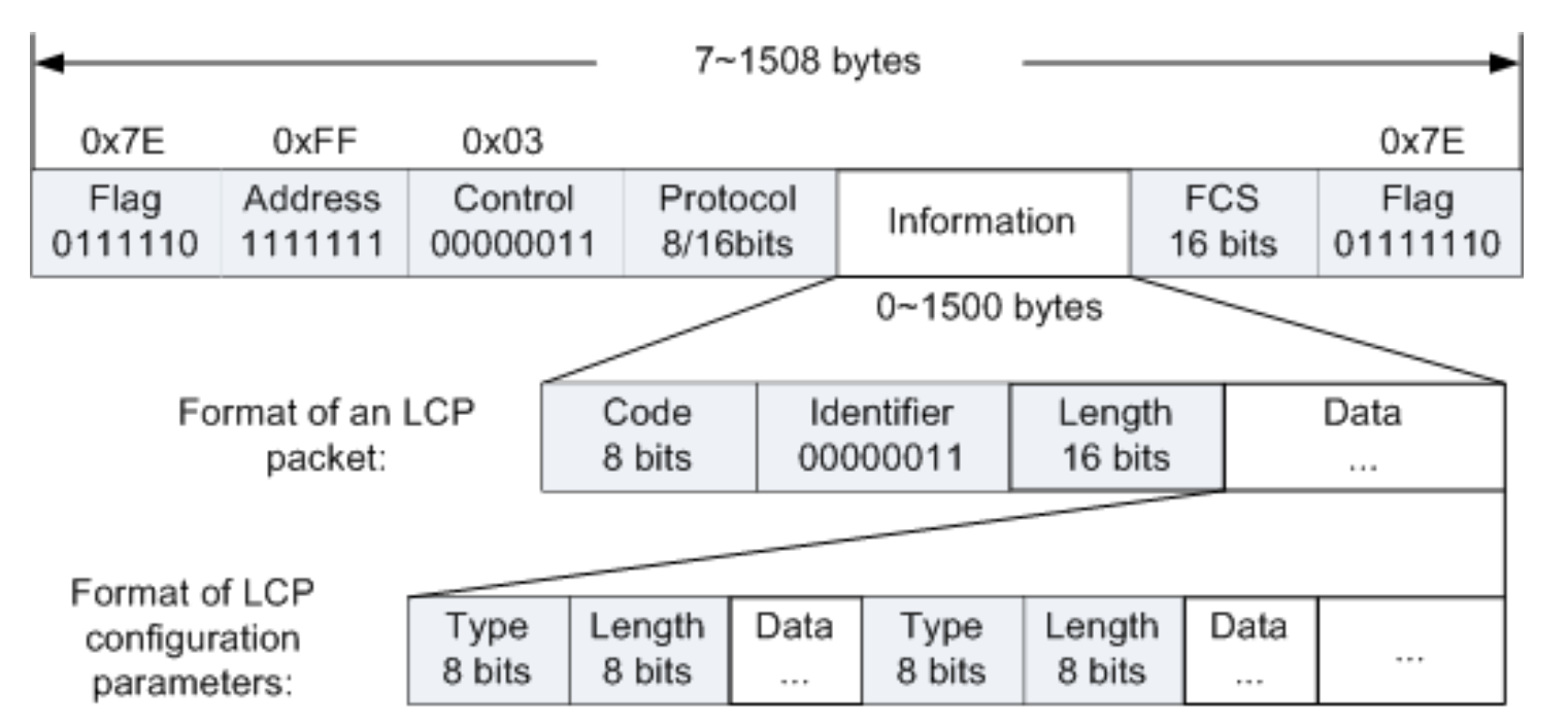
| Flag | 1 byte | The Flag field identifies the beginning and end of a physical frame, and the byte is 0x7E |
| Address | 1 byte | PPP protocol is applied to the point-to-point link. It can uniquely identify the other party, so there is no need to know the other party's data link layer address. Therefore, this byte has no meaning and is filled with all 1 broadcast addresses according to the protocol |
| Control | 1 byte | Like the Address field, the Control field of PPP data frame has no practical significance. The specified value is 0x03. This field identifies PPP message together with the Address field, that is, the PPP message header is FF03 |
| Protocol | 1 byte or 2 bytes | The protocol domain can be used to distinguish the contents of the data message carried by the information domain in the PPP data frame. The content of the protocol domain must comply with the provisions given in the address extension mechanism of ISO 3309. This mechanism stipulates that the contents filled in the protocol domain must be odd, that is, the lowest bit of the low byte is "1" and the lowest bit of the high byte is "0". If the protocol domain field of the PPP data frame sent by the sender does not comply with the above provisions, the receiver will consider the data frame unrecognizable. The receiver sends a protocol reject message to the sender, and the protocol number of the rejected message will be filled in the tail of the message. |
| Information | 0 ~ 1500 bytes | The maximum length of the information field is 1500 bytes, including the contents of the filled field. The maximum length of the information domain is equal to the default value of MRU (Maximum Receive Unit) in the PPP protocol. In practical application, the maximum package length option of information domain can be negotiated according to actual needs. If the length of the information field is less than 1500 bytes, it can be filled, but it is not necessary. If it is filled, both ends of the communication parties shall be able to identify useful and useless information before normal communication |
| FCS | 0 / 1 / 2 bytes | The calculation scope of FCS domain is other domains except flag domain. The function of the verification domain is mainly to detect the correctness of PPP data frame transmission. Some transmission guarantee mechanisms are introduced into the data frame, which will introduce more overhead, which may increase the delay of application layer interaction. |
2.1.2 three protocol components of PPP
| Component name | effect |
|---|---|
| Data encapsulation mode | Define the method of encapsulating multi protocol packets |
| Link Control Protocol | Define methods for establishing, negotiating, and testing data link layer connections |
| Network Control Protocol | It contains a set of protocols for connection establishment and parameter negotiation of different network layer protocols |
2.1.3PPP protocol state machine

| state | interpretation |
|---|---|
| Link static | The link must start and end at this stage. When an external event (such as carrier listening or network administrator setting) indicates that the physical layer is ready, PPP will enter the link establishment phase. At this stage, the LCP automatic machine will be in the initial state, and the conversion to the link establishment stage will send an UP event signal to the LCP automatic machine |
| Link establishment status | LCP is used to exchange configuration packets and establish connections. Once a configure ACK packet is sent and received, the exchange is completed and the LCP is turned on. All configuration options assume default values unless changed by the configuration exchange. It should be noted that only configuration options that do not depend on special network layer protocols are configured by LCP. In the network layer protocol stage, the configuration of individual network layer protocols is handled by individual network control protocol (NCP). Any non LCP packets received at this stage must be silently discarded. Receiving the LCP configuration request can return the link from the network layer protocol stage or authentication stage to the link establishment stage |
| Certification phase | On some links, one end of the link may need peer to authenticate it before allowing network layer protocol packets to be exchanged. Authentication is not mandatory. If a peer wants to authenticate according to a specific authentication protocol, it must require that authentication protocol be used in the link establishment phase. Authentication should be performed as soon as possible after the link is established. Link quality checks can occur simultaneously. It is forbidden to advance from the authentication stage to the network layer protocol stage until the authentication is completed. If the authentication fails, the authenticator should jump to the link termination stage. In this stage, only the packets of link control protocol, authentication protocol and link quality monitoring protocol are allowed. Other packets received in this stage must be quietly discarded. |
| Network layer protocol phase | Once PPP completes the previous stage, each network layer protocol (such as IP, IPX, or AppleTalk) must be set separately by the appropriate network control protocol (NCP). For example, NCP can assign a temporary IP address to the newly accessed PC, so that the PC will become a host on the Internet. Each NCP can be Opened and closed at any time. When an NCP is in the Opened state, PPP will carry the corresponding network layer protocol packets. When the corresponding NCP is not in the Opened state, any received supported network layer protocol packets will be quietly discarded |
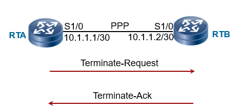
| Link termination phase | PPP can Terminate the link at any time. There are many reasons for link termination: carrier loss, authentication failure, link quality failure, idle cycle timer expiration, or administrator closing the link. The LCP terminates the link by exchanging Terminate packets. When the link is being closed, PPP notifies the network layer protocol so that they can take the correct action. After exchanging Terminate packets, the execution should notify the physical layer of disconnection in order to force link termination, especially when authentication fails. The sender of the Terminate request should disconnect after receiving the Terminate ACK or after the restart counter expires. The party receiving the Terminate request should wait for peer to cut off. After sending the Terminate request, it is allowed to cut off after at least one restart time. PPP should advance to the link death phase. Any non LCPpackets received at this stage must be quietly discarded |
2.1.4 link control LCP
- Message used for LCP link layer negotiation
| Message type | Function description |
|---|---|
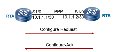
| Configure-Request | Contains a list of parameters used when the sender attempts to establish a connection with the opposite end |
| Configure-Ack | Indicates that the parameter value of the configure request sent by the opposite end is fully accepted |
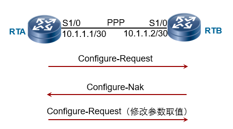
| Configure-Nak | Indicates that the parameter value in the configure request sent by the peer is illegal locally |
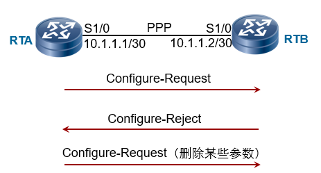
| Configure-Reject | Indicates that the parameters in the configure request sent by the peer are not recognized locally |
- LCP link negotiation process
- Successful negotiation
- Unsuccessful negotiation
- Parameter not recognized
- Common link parameters for LCP negotiation
| Parameter name | Function description | Negotiation rules | Default value |
|---|---|---|---|
| Maximum receiving unit MRU | Total length of Information field and Padding field in PPP data frame | Use the minimum value set at both ends | 1500 |
| Authentication protocol | Authentication protocol used by authentication peer | The authenticated party must support the authentication protocol used by the authenticator and configure it correctly, otherwise the negotiation will not succeed | Not certified |
| Magic number | Magic word is a randomly generated number used to detect the link loop. If the magic word in the received LCP message is the same as the locally generated magic word, it is considered that the link has a loop | If one end supports and the other end does not, it means that the link has no loop, and the negotiation is considered successful; If both ends support, the detection mechanism is used to detect the loop | Enable |
- LCP close link
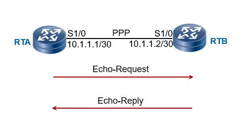
- LCP detects link status
2.1.5 PPP authentication protocol
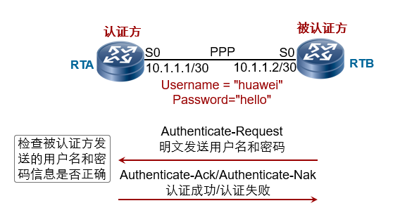
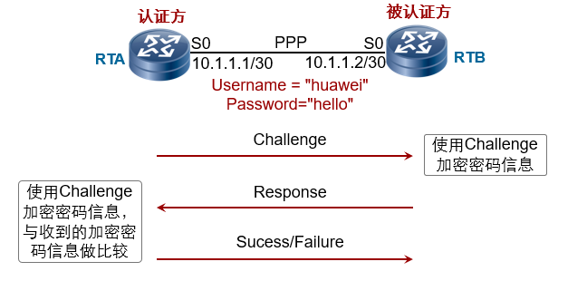
There are two PPP authentication methods: PAP (plaintext) and CHAP (ciphertext):
- PAP authentication mode
- CHAP authentication mode
2.1.6 network control protocol NCP
| Agreement name | purpose |
|---|---|
| IPCP | It is used to negotiate control IP parameters so that PPP can be used to transmit IP packets |
| MPLSCP | It is used to negotiate and control MPLSCP protocol parameters so that PPP can be used to transmit MPLSCP packets |
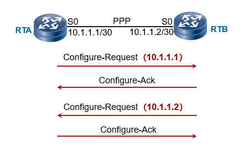
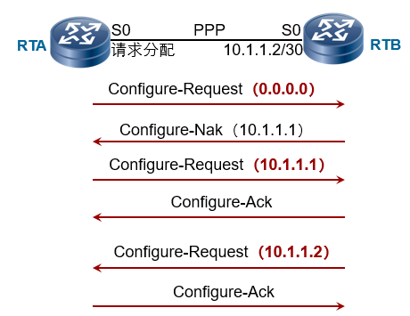
- Negotiating IP addresses using IPCP - static configuration
- Negotiating IP addresses using IPCP - dynamic negotiation
2.2 PPP configuration method
Experimental topology:
2.2.1 simple PPP configuration on serial link
AR1:
<Huawei>system-view
[Huawei]interface Serial 1/0/0
[Huawei-Serial1/0/0]link-protocol ppp
[Huawei-Serial1/0/0]ip address 10.1.1.1 255.255.255.252
[Huawei-Serial1/0/0]quit
The same is true for AR2.
2.2.2 PAP authentication mode of PPP
The experimental topology is the same as above
AR1:
<Huawei>system-view
[Huawei]aaa
[Huawei-aaa]local-user huawei password cipher huawei@123
[Huawei-aaa]local-user huawei service-type ppp
[Huawei-aaa]quit
[Huawei]interface Serial 1/0/0
[Huawei-Serial1/0/0]link-protocol ppp
[Huawei-Serial1/0/0]ppp authentication-mode pap
[Huawei-Serial1/0/0]ip address 10.1.1.1 255.255.255.252
[Huawei-Serial1/0/0]quit
AR2:
<Huawei>system-view
[Huawei]interface Serial 1/0/0
[Huawei-Serial1/0/0]link-protocol ppp
[Huawei-Serial1/0/0] ppp pap local-user huawei password cipher huawei@123
[Huawei-Serial1/0/0]ip address 10.1.1.2 255.255.255.252
[Huawei-Serial1/0/0]quit
2.2.3 CHAP authentication mode of PPP
AR1:
<Huawei>system-view
[Huawei]aaa
[Huawei-aaa]local-user huawei password cipher huawei@123
[Huawei-aaa]local-user huawei service-type ppp
[Huawei-aaa]quit
[Huawei]interface Serial 1/0/0
[Huawei-Serial1/0/0]link-protocol ppp
[Huawei-Serial1/0/0]ppp authentication-mode chap
[Huawei-Serial1/0/0]ip address 10.1.1.1 255.255.255.252
[Huawei-Serial1/0/0]quit
AR2:
<Huawei>system-view
[Huawei]interface Serial 1/0/0
[Huawei-Serial1/0/0]link-protocol ppp
[Huawei-Serial1/0/0]ppp chap user huawei
[Huawei-Serial1/0/0]ppp chap password cipher huawei@123
[Huawei-Serial1/0/0]ip address 10.1.1.2 255.255.255.252
[Huawei-Serial1/0/0]quit
2.2.4 IPCP dynamic negotiation IP address
AR1:
<Huawei>system-view
[Huawei]interface Serial 1/0/0
[Huawei-Serial1/0/0]link-protocol ppp
[Huawei-Serial1/0/0]ip address ppp-negotiate
[Huawei-Serial1/0/0]quit
AR2:
<Huawei>system-view
[Huawei]interface Serial 1/0/0
[Huawei-Serial1/0/0]link-protocol ppp
[Huawei-Serial1/0/0]remote address 10.1.1.1
[Huawei-Serial1/0/0]ip address 10.1.1.2 255.255.255.252
[Huawei-Serial1/0/0]quit
Experimental results:
3, FR principle and configuration
Frame relay is a connection oriented data link layer technology. It is mainly used for LAN interconnection and WAN connection on public or private networks. Frame relay is a simplified X.25 WAN protocol. Like HDLC and PPP, frame relay DR works at the data link layer.
3.1 FR principle
Frame relay technology is a fast packet switching technology that transmits and exchanges data units in a simplified way at the data link layer. Frame relay adopts virtual circuit technology.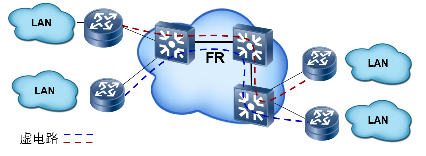
Frame relay protocol is a simplified X.25 protocol with the following characteristics:
- The control layer provides the functions of virtual circuit management, bandwidth management and blocking prevention.
- The physical circuit implements statistical time division multiplexing, that is, multiple logical connections can be multiplexed on one physical connection, which realizes the multiplexing and dynamic allocation of bandwidth, is conducive to multi-user and multi rate data transmission, and makes full use of network resources.
- The processing processes of error control, acknowledgement retransmission, flow control and congestion avoidance in packet switching network are simplified, the processing time is shortened and the utilization of digital transmission channel is improved.
3.1.1 frame relay network
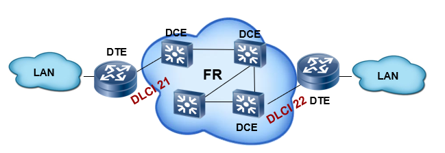
- The user equipment is called Data Terminal Equipment (DTE).
- The equipment that provides access for user equipment belongs to network equipment and is called data circuit terminating equipment (DCE)
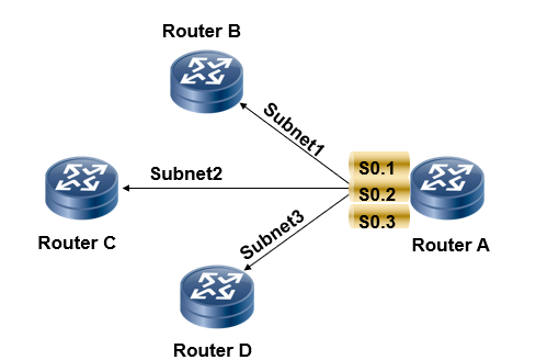
- Frame relay protocol is a statistical multiplexing protocol, which can provide multiple virtual circuits on a single physical transmission line. Each virtual circuit is identified by Data Link Connection Identifier DLCI (data link connection identifier). DLCI is only valid in the local interface and the peer interface directly connected to it, and does not have global validity, that is, in the frame relay network, the same DLCI on different physical interfaces does not mean that it is the same virtual circuit. The value range of DLCI available to users is 16 ~ 1022, of which 1007 ~ 1022 are reserved DLCI. Get the allocated DLCI from the frame relay network service provider. Each DLCI has only local meaning and maps the network address of the opposite end to the DLCI.
Forwarding process: when the router connected to the frame relay network receives a packet, it first looks up its routing table according to the destination address and finds the next hop router; Then search the frame relay mapping table according to the next hop router to find the DLCI number of the corresponding virtual link that can reach the next hop router; The packet is then transmitted from this virtual link. When the frame relay switch receives the packet, it looks up the frame relay switch table and finds the outgoing port and DLCI number according to the incoming port and DLCI number of the packet; Then, the data packet is exchanged to the DLCI of the exit to complete the transmission of the data packet. Other switches in the FR network do similar processing, and finally reach the next hop router to complete the relay function of the frame relay network.
3.1.2 frame relay interface type
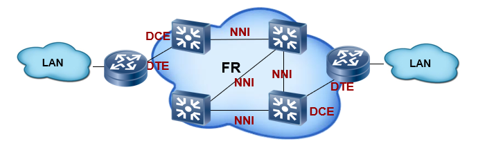
- DTE (Data Terminal Equipment)
- DCE (data circuit terminating equipment)
- NNI (network to network interface)
3.1.3 virtual circuit
Frame relay is a connection oriented technology. A connection must be established before communication. The connection established between DTE s is called virtual circuit. There are two types of frame relay virtual circuits: PVC and SVC.
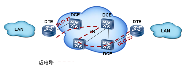
- Permanent Virtual Circuit PVC (Permanent Virtual Circuit): a fixed virtual circuit provided to the user. Once the virtual circuit is established, it will take effect permanently unless deleted manually. PVC is generally used for frequent and stable data transmission between two ends. At present, the most used mode in frame relay is Permanent Virtual Circuit.
- Switched Virtual Circuit SVC (Switched Virtual Circuit): a virtual circuit automatically allocated through the protocol. After communication, the virtual circuit will be automatically cancelled. General burst data transmission uses SVC.
3.1.4 LMI negotiation - local management interface
LMI (Local Management Interface): Local Management Interface used to monitor the status of permanent virtual circuits.
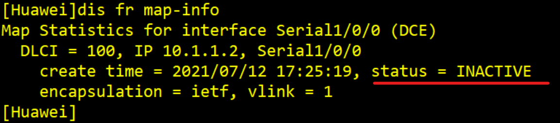
LMI protocol maintains the link status and PVC status of frame relay through status query message and status response message. When the LMI negotiation message of the equipment at both ends is sent and received correctly, the PVC status will change to Active status.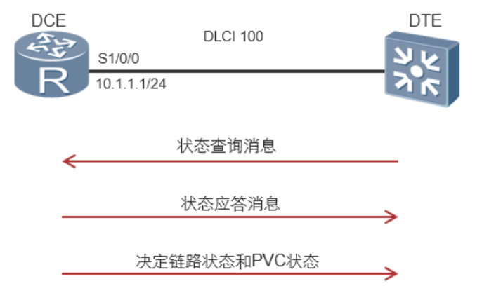
3.1.5 frame relay address mapping
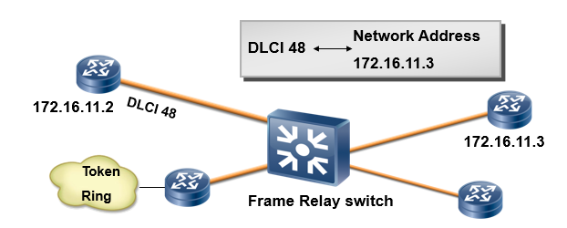
- Frame relay address mapping (MAP) is to associate the protocol address (IP or IPX address) of the peer device with the DLCI locally arriving at the peer device.
- The address mapping table can be manually configured or dynamically maintained by the reverse ARP protocol.
3.1.6 reverse ARP negotiation (reverse address resolution protocol InARP)
The main function of Reverse Address Resolution Protocol (ARP) is to obtain the IP address of the opposite device of virtual circuit
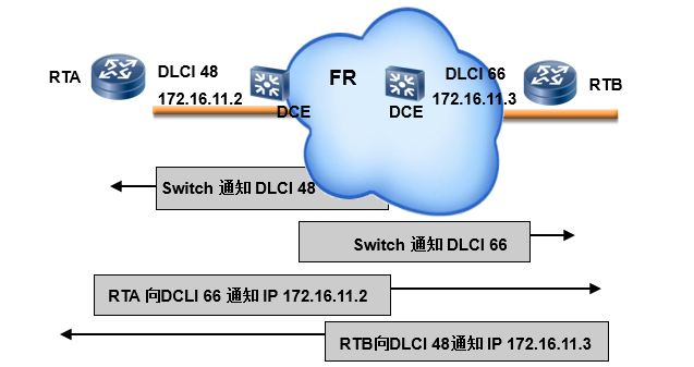
The negotiation process of InARP is as follows:
- If the IP address is configured on the local interface, the device will send the reverse ARP request message to the opposite device on the virtual circuit. The request message contains the local IP address.
- After receiving the request, the opposite device can obtain the IP address of the local device, generate an address mapping, and send an Inverse ARP response message to respond.
- After receiving the reverse ARP response message, the local end parses the IP address of the opposite end in the message and also generates address mapping.
3.1.7 frame relay horizontal segmentation and sub interface
- Horizontal segmentation: in order to reduce the generation of routing loops, the horizontal segmentation mechanism of the routing protocol does not allow the router to send the routing update information received from an interface from the interface.
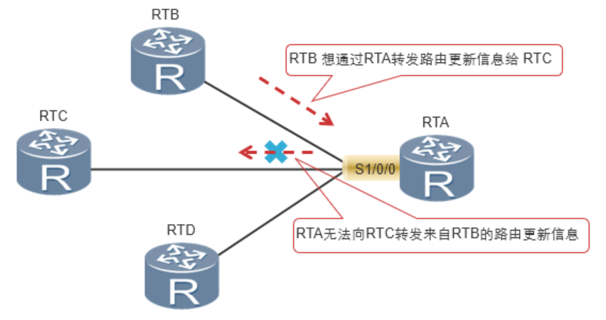
The RTB announces a route information to the RTA, but due to the horizontal segmentation mechanism, the RTA cannot forward the route information to the RTC through the Serial1/0/0 interface receiving the route information. - Sub interface: configure multiple sub interfaces on a physical interface, and each sub interface uses a virtual circuit to connect to the opposite router, so as to solve the problem caused by horizontal segmentation.
A physical interface can contain multiple logical sub interfaces, and each sub interface uses one or more dlcis to connect to the peer router.
3.2 FR configuration method
3.2.1 static parsing configuration
Experimental topology: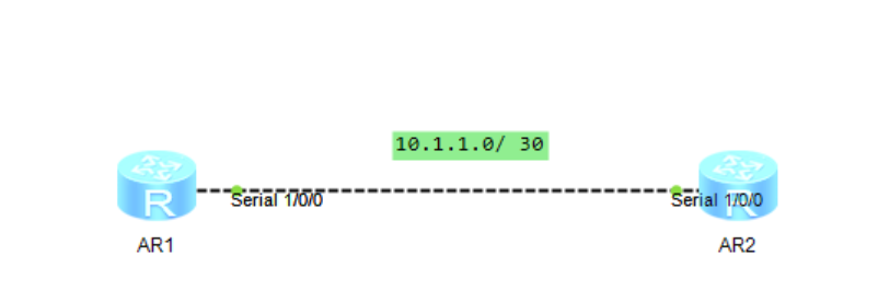
AR1:
<Huawei>system-view
[Huawei]interface Serial 1/0/0
[Huawei-Serial1/0/0]link-protocol fr ietf
[Huawei-Serial1/0/0]fr interface-type dce
[Huawei-Serial1/0/0]fr dlci 100
[Huawei-fr-dlci-Serial1/0/0-100]quit
[Huawei-Serial1/0/0]undo fr inarp
[Huawei-Serial1/0/0]ip address 10.1.1.1 255.255.255.252
[Huawei-Serial1/0/0]fr map ip 10.1.1.2 100
[Huawei-Serial1/0/0]quit
Only AR1 is configured
AR2:
<Huawei>system-view
[Huawei]interface Serial 1/0/0
[Huawei-Serial1/0/0]link-protocol fr ietf
[Huawei-Serial1/0/0]fr interface-type dte
[Huawei-Serial1/0/0]undo fr inarp
[Huawei-Serial1/0/0]ip address 10.1.1.2 255.255.255.252
[Huawei-Serial1/0/0]fr map ip 10.1.1.1 100
[Huawei-Serial1/0/0]quit
Experimental results: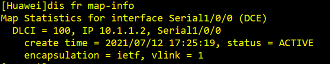
3.2.2 dynamic parsing configuration
Experimental topology:
AR1:
<Huawei>system-view
[Huawei]interface Serial 1/0/0
[Huawei-Serial1/0/0]link-protocol fr ietf
[Huawei-Serial1/0/0]fr interface-type dce
[Huawei-Serial1/0/0]fr dlci 100
[Huawei-fr-dlci-Serial1/0/0-100]quit
[Huawei-Serial1/0/0] fr inarp
[Huawei-Serial1/0/0]ip address 10.1.1.2 255.255.255.252
[Huawei-Serial1/0/0]quit
AR2:
<Huawei>system-view
[Huawei]interface Serial 1/0/0
[Huawei-Serial1/0/0]link-protocol fr ietf
[Huawei-Serial1/0/0]fr interface-type dte
[Huawei-Serial1/0/0] fr inarp
[Huawei-Serial1/0/0]ip address 10.1.1.2 255.255.255.252
[Huawei-Serial1/0/0]quit
Experimental results: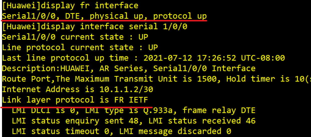
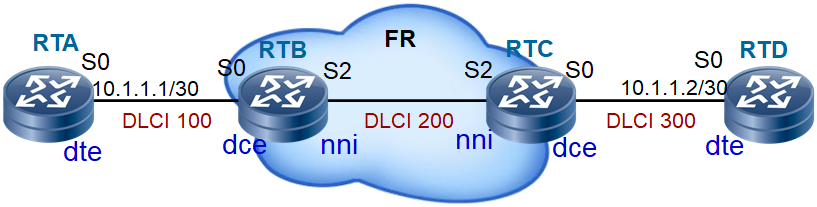
3.2.3 static routing configuration of frame relay switching
Experimental topology: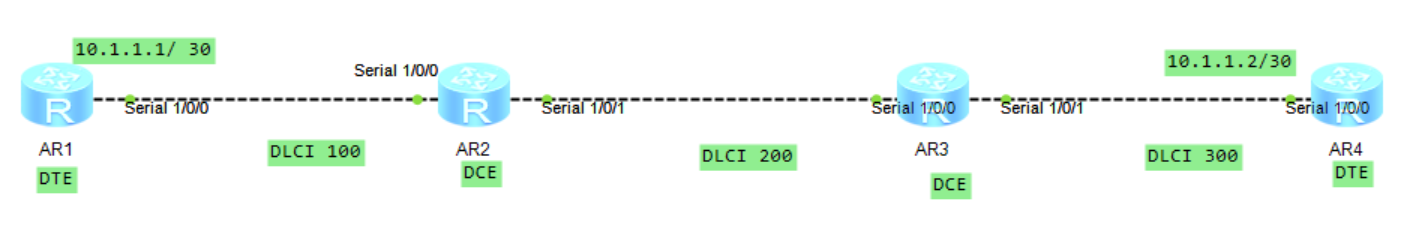
AR1:
<Huawei>system-view
[Huawei]interface Serial1/0/0
[Huawei-Serial1/0/0]link-prorocol fr ietf
[Huawei-Serial1/0/0]fr interface-type dte
[Huawei-Serial1/0/0]ip address 10.1.1.1 30
AR2:
<Huawei>system-view
[Huawei]fr swiching
[Huawei]interface Serial1/0/0
[Huawei-Serial1/0/0]link-prorocol fr ietf
[Huawei-Serial1/0/0]fi interface-type dce
[Huawei-Serial1/0/0]fr dlci 100
[Huawei-fr-dlci-Serial1/0/0-100]quit
[Huawei-Serial1/0/0]fr dlci-swithing 100 interface Serial1/0/1 dlci 200
[Huawei-Serial1/0/0]quit
[Huawei]interface Serial1/0/1
[Huawei-Serial1/0/1]link-procotol ft ietf
[Huawei-Serial1/0/1]fr interface-type nni
[Huawei-Serial1/0/1]fr dlci 200
[Huawei-fr-dlci-Serial1/0/1-200]quit
[Huawei-Serial1/0/1]fr dlci-swich 200 interface Serial1/0/0 dlci 100
[Huawei-Serial1/0/1]quit
AR3:
<Huawei>system-view
[Huawei]fr swiching
[Huawei]interface Serial1/0/0
[Huawei-Serial1/0/0]link-prorocol fr ietf
[Huawei-Serial1/0/0]fi interface-type nni
[Huawei-Serial1/0/0]fr dlci 200
[Huawei-fr-dlci-Serial1/0/0-200]quit
[Huawei-Serial1/0/0]fr dlci-swithing 200 interface Serial1/0/1 dlci 300
[Huawei-Serial1/0/0]quit
[Huawei]interface Serial1/0/1
[Huawei-Serial1/0/1]link-procotol ft ietf
[Huawei-Serial1/0/1]fr interface-type dce
[Huawei-Serial1/0/1]fr dlci 300
[Huawei-fr-dlci-Serial1/0/1-200]quit
[Huawei-Serial1/0/1]fr dlci-swich 300 interface Serial1/0/0 dlci 200
[Huawei-Serial1/0/1]quit
AR4:
<Huawei>system-view
[Huawei]interface Serial1/0/0
[Huawei-Serial1/0/0]link-prorocol fr ietf
[Huawei-Serial1/0/0]fi interface-type dte
[Huawei-Serial1/0/0]ip address 10.1.1.2 30
Huawei AR2220 does not support fr DLCI switching 200 interface Serial1 / 0 / 1 DLCI 300 command, so the experiment cannot be completed. Therefore, the frame relay switch is used to complete the experiment. The topology is as follows:
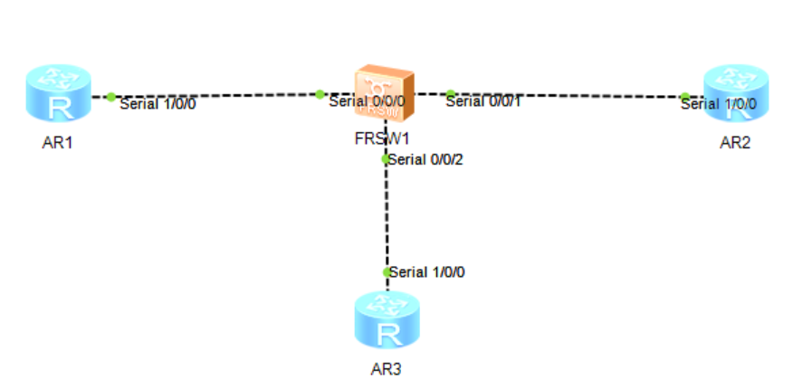
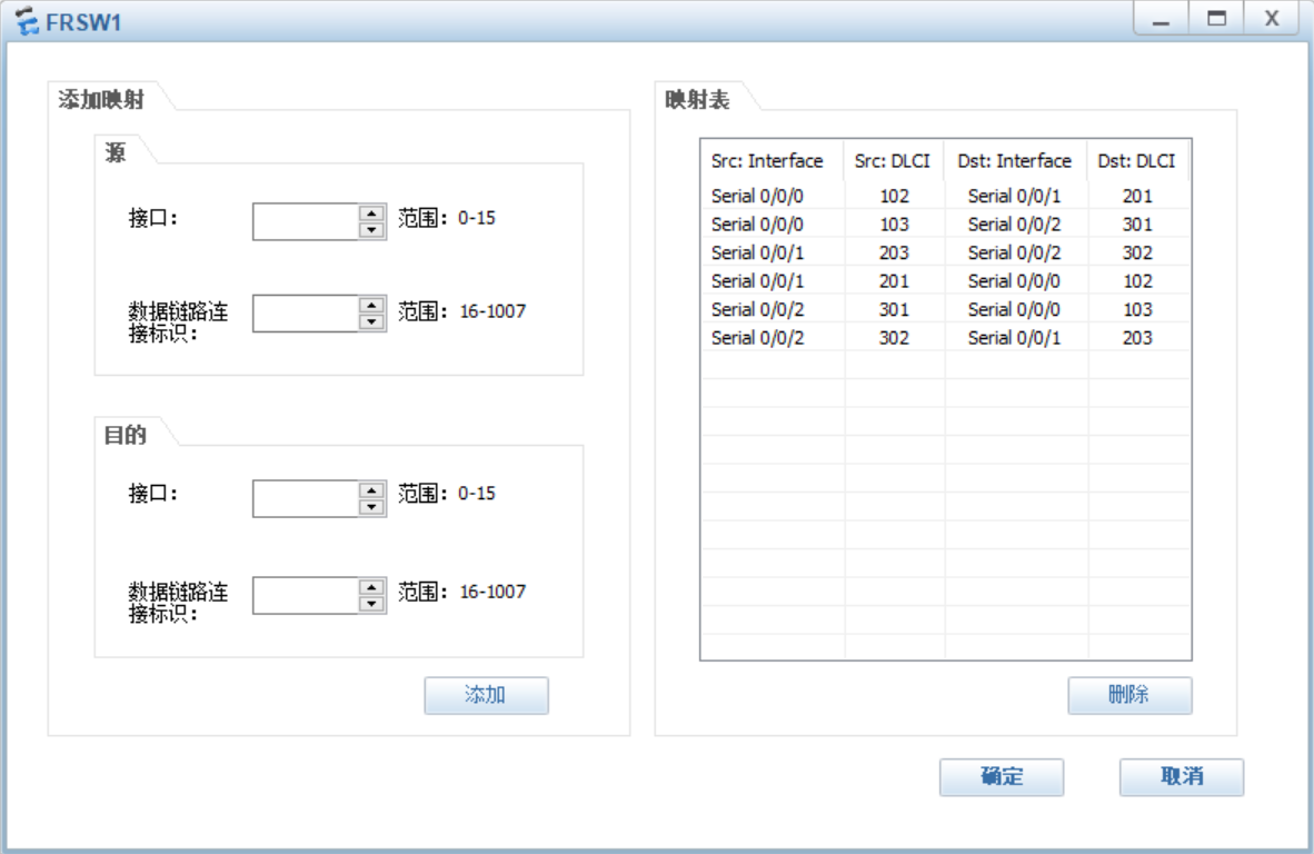
Frame relay switch configuration:
AR1:
<Huawei>system-view
[Huawei]interface Serial 1/0/0
[Huawei-Serial1/0/0]link-protocol fr ietf
[Huawei-Serial1/0/0]undo fr inarp
[Huawei-Serial1/0/0]fr dlci 102
[Huawei-fr-dlci-Serial1/0/0-102]quit
[Huawei-Serial1/0/0]fr dlci 103
[Huawei-fr-dlci-Serial1/0/0-103]quit
[Huawei-Serial1/0/0]fr map ip 10.1.1.2 102
[Huawei-Serial1/0/0]fr map ip 10.1.1.3 103
[Huawei-Serial1/0/0]ip address 10.1.1.1 255.255.255.248
[Huawei-Serial1/0/0]quit
[Huawei]ospf 1
[Huawei-ospf-1]peer 10.1.1.2
[Huawei-ospf-1]peer 10.1.1.3
[Huawei-ospf-1]area 0
[Huawei-ospf-1-area-0.0.0.0]network 10.1.1.0 0.0.0.7
[Huawei-ospf-1-area-0.0.0.0]quit
[Huawei-ospf-1]quit
AR2:
<Huawei>system-view
[Huawei]interface Serial 1/0/0
[Huawei-Serial1/0/0]link-protocol fr ietf
[Huawei-Serial1/0/0]undo fr inarp
[Huawei-Serial1/0/0]fr dlci 201
[Huawei-fr-dlci-Serial1/0/0-201]quit
[Huawei-Serial1/0/0]fr dlci 203
[Huawei-fr-dlci-Serial1/0/0-203]quit
[Huawei-Serial1/0/0]fr map ip 10.1.1.1 201
[Huawei-Serial1/0/0]fr map ip 10.1.1.3 203
[Huawei-Serial1/0/0]ip address 10.1.1.2 255.255.255.248
[Huawei-Serial1/0/0]quit
[Huawei]ospf 1
[Huawei-ospf-1]peer 10.1.1.1
[Huawei-ospf-1]peer 10.1.1.3
[Huawei-ospf-1]area 0
[Huawei-ospf-1-area-0.0.0.0]network 10.1.1.0 0.0.0.7
[Huawei-ospf-1-area-0.0.0.0]quit
[Huawei-ospf-1]quit
AR3:
<Huawei>system-view
[Huawei]interface Serial 1/0/0
[Huawei-Serial1/0/0]link-protocol fr ietf
[Huawei-Serial1/0/0]undo fr inarp
[Huawei-Serial1/0/0]fr dlci 301
[Huawei-fr-dlci-Serial1/0/0-301]quit
[Huawei-Serial1/0/0]fr dlci 302
[Huawei-fr-dlci-Serial1/0/0-302]quit
[Huawei-Serial1/0/0]fr map ip 10.1.1.1 301
[Huawei-Serial1/0/0]fr map ip 10.1.1.2 302
[Huawei-Serial1/0/0]ip address 10.1.1.3 255.255.255.248
[Huawei-Serial1/0/0]quit
[Huawei]ospf 1
[Huawei-ospf-1]peer 10.1.1.1
[Huawei-ospf-1]peer 10.1.1.2
[Huawei-ospf-1]area 0
[Huawei-ospf-1-area-0.0.0.0]network 10.1.1.0 0.0.0.7
[Huawei-ospf-1-area-0.0.0.0]quit
[Huawei-ospf-1]quit
3.2.4 PVC configuration of frame relay switching
[Huawei]fr switching
[Huawei]fr switch 1 interface Serial1/0/0 dlci 100 interface Serial1/0/1 dlci 200
[Huawei]fr switching
[Huawei]fr switch 2 interface Serial1/0/0 dlci 200 interface Serial1/0/1 dlci 300