Huawei BGP dynamic routing protocol theory + experiment
Article directory
Preface
1: BGP protocol theory
1.1: Overview
1.2: classification of dynamic routes
1.2.1: classification by autonomous system
1.2.2: classification by agreement type
1.3: characteristics of BGP
1.4: working principle of BGP
1.4.1: BGP message
1.4.2: BGP database
1.4.3: type of BGP
2: BGP protocol experiment
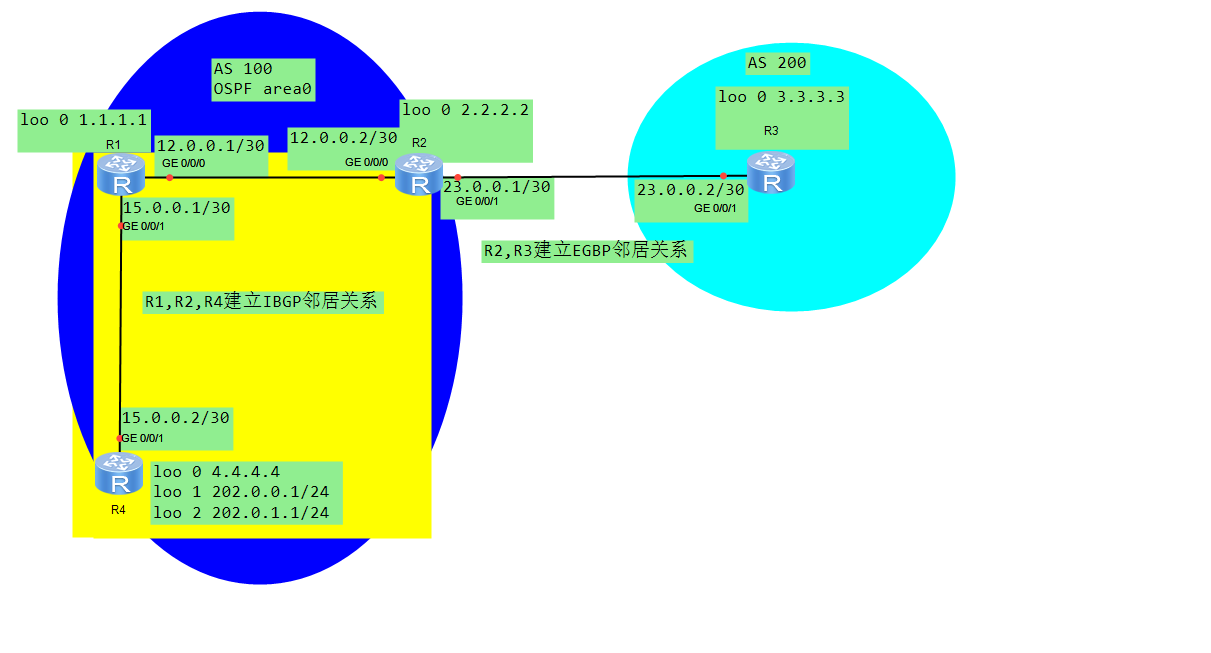
2.1: experimental environment
2.2: purpose of the experiment
2.3: experimental topology
2.4: experiment process
2.4.1 command explanation
2.4.2: practical operation
2.5: experimental verification
2.6: experiment summary
1: BGP protocol theory
1.1: Overview
BGP is a dynamic routing protocol running between AS and AS, and its main function is to automatically exchange acyclic routing information between AS
In order to eliminate the routing loop and implement the user configured routing strategy, the topology of AS is constructed.
At present, there are many public network entries, IGP protocol can not be carried, and BGP can easily deal with it. Generally, BGP protocol is used for routing information exchange between ISP and ISP, or between cross domain regional headquarters and branches
Self made system No
Autonomous system (AS) is a set of routers managed by a technical management organization and using a unified routing strategy
Autonomous system number range: 1-65535, where 1-64511 is the public AS number registered on the Internet, similar to the public IP address.
64512-65535 is the private AS number, similar to the private IP address
www.inna.org, registration website (individuals cannot register)
1.2: classification of dynamic routes
1.2.1: classification by autonomous system
IGP
Internal routing protocol of autonomous system, mainly including RIP1/RIP2, OSPF, ISIS, EIGRP (Cisco private protocol)
IGP is a routing protocol running in AS, which mainly solves the routing problem in AS, finds and calculates routes
EGP
Routing protocol between autonomous systems, usually BGP
EGP is a routing protocol running between AS and AS, which solves the problem of routing between AS.
1.2.2: classification by agreement type
Distance vector routing protocol
rip1/2, BGP (path vector protocol), EIGRP (Advanced Distance Vector Protocol)
Link state routing protocol
OSPF, ISIS: using SPF shortest path algorithm
Characteristics of 1.3:BGP
Transmission protocol: TCP, port 179
BGP is an external routing protocol used to transfer routing information between AS
Is an enhanced path vector routing protocol
Reliable route update mechanism
Rich Metric measurement methods
No loop protocol design
Attach multiple attribute information to route entries
Support CIDR (no category inter domain routing)
Rich routing filtering and routing strategies
No periodic updates required
Send only incremental routes when updating routes
Periodically send KeepAlive message to maintain TCP connectivity
1.4: working principle of BGP
1.4.1: BGP message
Open message
Opten message is the first message sent after the establishment of TCP, which is used to establish the connection relationship between BGP peers, mainly including BGP version number, local AS number, Holdtime and other information
UPdate message
The Update message is used to Update the routing information between bgps. The Update message can announce multiple reachable routing information with the same attribute, and can also cancel multiple unattainable routing information
Notification message
The function of the message is to send the notification message to the peer immediately when BGP detects the error status, and then BGP will interrupt and return to idle status as long as it receives the notification message
Route refresh message
It is used to inform the peer of the refresh capability of the route supported by the BGP. The entry policy route of BGP changes. The local BGP route will send route refresh message to the peer. After receiving the message, the peer will send its route information to the local BGP router again
KeepAlive message
This message is sent periodically between peers to maintain the validity of the connection and maintain its connection. The KeepAlive message has only one BGP header. The default KeepAlive message sending cycle is 60S and the holding time is 180S. This is similar to the Hello message in OSPF
1.4.2: BGP database
IP routing table: global routing information base, including optimal IP routing information
BGP routing table: BGP routing information base, including the routing information advertised by local BGPSpeak, which is added to the routing table optimally
Neighbor table: peer neighbor list table, including neighbor information and neighbor list at both ends of peer
ADI rib in: unprocessed routing information base declared by peer to local Speak
Adjust-RIB-OUT: local Speak is declared to the specified peer routing information base
1.4.3: type of BGP
Two neighbors: IBGP and EBGP
IBGP: BGP neighbor relationship within the same AS. IBGP neighbor refers to the peer running BGP protocol whose two ends are in the same AS domain, belonging to BGP AS internal
EBGP: BGP neighbor relationship between AS. EBGP usually refers to the peer running BGP protocol whose two ends are inside different AS
2: BGP protocol experiment
2.1: experimental environment
eNSP software
4 routers (R1,R2,R3,R5)
R1, R2 and R4 are in OSPF area 0 and AS100
R3 in AS200
2.2: purpose of the experiment
Realize the whole network interworking through configuration
2.3: experimental topology

2.4: experiment process
2.4.1 command explanation
BGP configuration ideas
1. Enable BGP, followed by AS system number
2. It is used to announce route ID and establish neighbor relationship. Since OSPF protocol is included in this, route ID can be announced before BGP is started, reducing one operation step
3. Announce who to build a neighbor relationship with
4. Announce BGP route, (network, import)
Command display
'//Establish neighborhood relationship '
[R1]router-id 1.1.1.1   '//Announce router ID '
[R1]bgp 100 '//Start bgp'
[R1-bgp]peer 7.7.7.7 as-number 100  '//The first step to establish a neighbor relationship is to announce the as area to be established. "
[R1-bgp]peer 7.7.7.7 connect-interface loo 0    '//The second step is to establish neighbor relationship. Use loo 0 address to establish neighbor relationship '
[R1-bgp]network 1.1.1.1 32  '//Announce segment '
'//View command '
[R1] display bgp peer       '//View BGP neighborhood '
[R1] display routing-table      '//View BGP routing table '
[R1-bgp] import-route ospf 1    '//Route injected into ospf/ISIS'
'//Only when the neighbor relationship is established can the injected routing information be learned by the neighbor
2.4.2: practical operation
I have directly given the result of the configuration command. You should all be able to chat with me or comment if you have any questions
R1 configuration
sysname R1      //Modify name

router id 1.1.1.1       //Announce router id

int g0/0/0      //Configure interface address
ip add 12.0.0.1 30

int g0/0/1      //Configure interface address
ip address 15.0.0.1 30

int loo 0           //Configure interface address
ip add 1.1.1.1 32

bgp 100         //Start bgp, 100 is the process number

peer 2.2.2.2 as-number 100      //The first step to establish a neighbor relationship with a route with router id of 2.2.2.2 and as area of 100 is to specify the other party
peer 2.2.2.2 connect-interface LoopBack0    //The second step of establishing neighbor relationship with router id 2.2.2.2 is to connect the other side with loo 0 interface
peer 4.4.4.4 as-number 100  //The first step to establish a neighbor relationship with a route with router id of 4.4.4.4 and as area of 100 is to specify the other party
peer 4.4.4.4 connect-interface LoopBack0    //The second step of establishing the neighbor relationship with the route with router id 4.4.4. Uses the loo 0 interface to connect the other side

network 1.1.1.1 255.255.255.255 //Announcement segment

ospf 1              //Start ospf process as 1
area 0.0.0.0            //Declare ospf area
network 1.1.1.1 0.0.0.0     //The following are declared segments
network 12.0.0.0 0.0.0.3

network 15.0.0.0 0.0.0.3
R2 configuration
sysname R2

router id 2.2.2.2

int g0/0/0
ip add 12.0.0.2 30

int g0/0/1
ip add 23.0.0.1 30

int loo 0
ip add 2.2.2.2 32

bgp 100
peer 1.1.1.1 as-number 100
peer 1.1.1.1 connect-interface LoopBack0
peer 4.4.4.4 as-number 100
peer 4.4.4.4 connect-interface LoopBack0
peer 23.0.0.2 as-number 200     //Directly use the physical address of 23.0.0.2 and the router in bgp200 area to establish the connection, and do not use the virtual interface address

network 2.2.2.2 255.255.255.255
import-route ospf 1     //Inject the route entry of ospf 1, otherwise R3 will not learn other route entries in bgp100. Except for R2's 2.2.2.2 announced in BGP, others will not learn, so it is necessary to inject the route entry of ospf 1 '

ospf 1
area 0.0.0.0
network 2.2.2.2 0.0.0.0
network 12.0.0.0 0.0.0.3

network 23.0.0.0 0.0.0.3
R3 configuration
sysname R3

router id 3.3.3.3

int g0/0/1
ip add 23.0.0.2 30

int loo 0
ip add 3.3.3.3 32

bgp 200
peer 23.0.0.1 as-number 100         //Use physical address 23.0.0.1 and bgp100 router to establish neighbor relationship

network 3.3.3.3 255.255.255.255
R4 configuration
sysname R5

router id 4.4.4.4

int g0/0/1
ip add 15.0.0.2 30

int loo 0
ip add 4.4.4.4 32

int loo 1
ip add 202.0.0.1 24

int loo 2
ip add 202.0.1.1 24

bgp 100
peer 1.1.1.1 as-number 100
peer 1.1.1.1 connect-interface LoopBack0
peer 2.2.2.2 as-number 100
peer 2.2.2.2 connect-interface LoopBack0

network 4.4.4.4 255.255.255.255

ospf 1
area 0
network 4.4.4.4 0.0.0.0
network 15.0.0.0 0.0.0.3
network 202.0.0.0 0.0.0.255
network 202.0.1.0 0.0.0.255
At this point, we can use dis IP routing table to find that we have learned all routing entries from each other
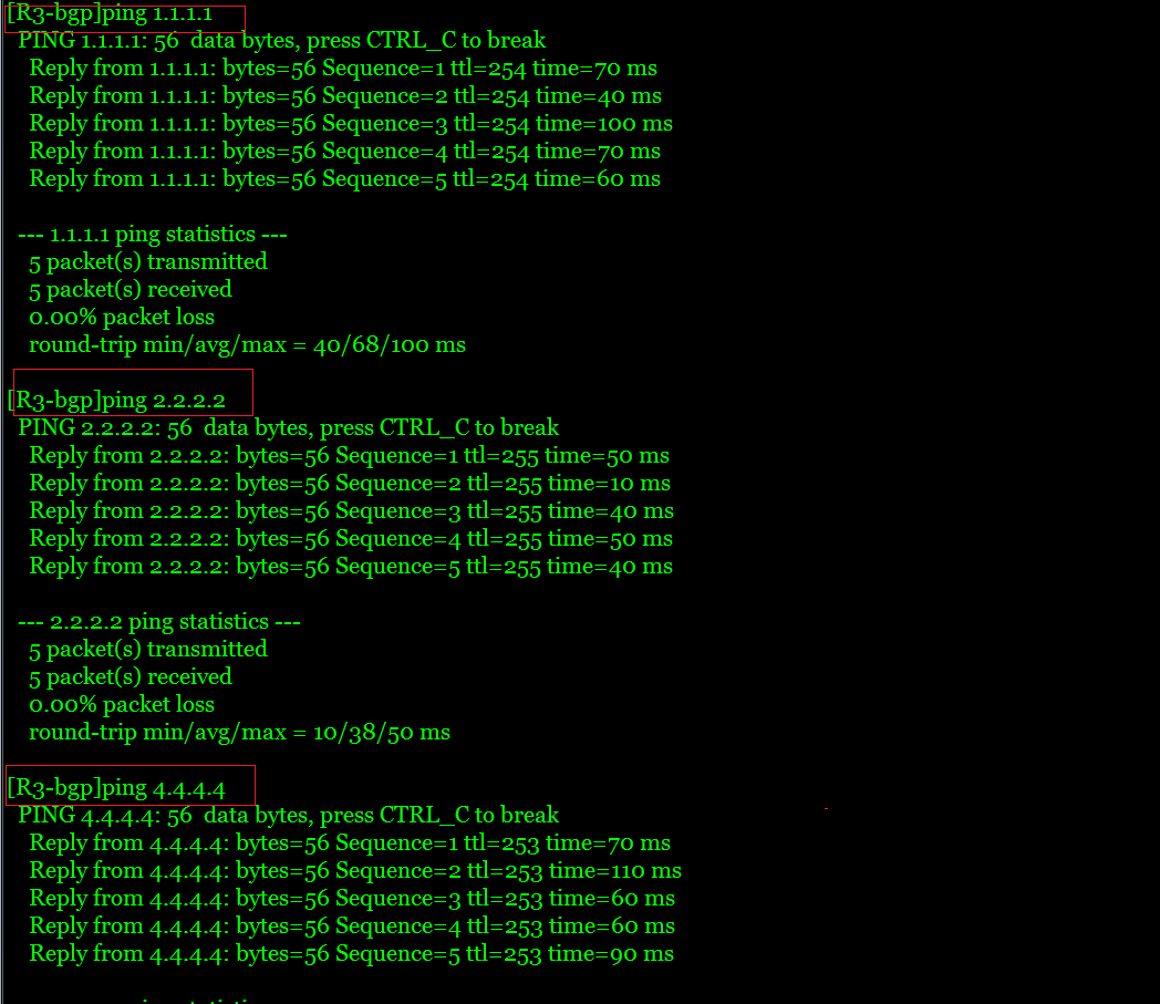
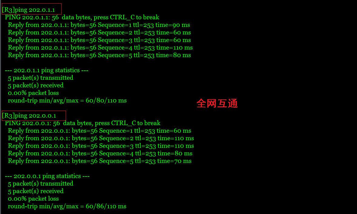
2.5: experimental verification
The whole network interworking is successful. Test several other routers in the same way


2.6: experiment summary
The physical address is needed to establish neighbor relationship across autonomous regions, otherwise the routing entry of the other party cannot be learned
In order to learn all the routing entries of each other's region, two routers that establish neighbor relationship across autonomous regions need each other to inject ospf or IS-IS routing entries
To establish a neighbor relationship across autonomous regions, if you want to use a virtual loopback address, you need to add a static route and point to the next one as two hops
'//Adding static route is not described in detail '
##R2##
[R2] router id 2.2.2.2
[R2] bgp 100
[R2-bgp] peer 3.3.3.3 as-number 200
[R2-bgp] peer 3.3.3.3 connect-interface LoopBack 0
[R2-bgp] peer 3.3.3.3 ebgp-max-hop 2

##R3##
[R3] router id 3.3.3.3
[R3] bgp 200
[R3-bgp] peer 2.2.2.2 as-number 100
[R3-bgp] peer 2.2.2.2 connect-interface LoopBack 0
[R3-bgp] peer 2.2.2.2 ebgp-max-hop 2
Keywords:
network
Database
Attribute
Added by sparrrow on Sat, 08 Feb 2020 10:29:40 +0200


