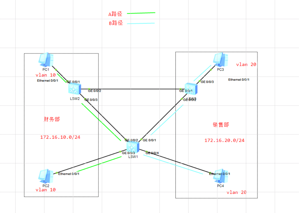
In STP, because STP has suboptimal path and other factors, we use MSTP protocol to complete this experiment. MSTP can better solve some problems in the network, and MSTP is also compatible with STP and RSTP.
Next, we see the configuration implementation:
Step 1: first, we add a P address to the PC
I believe you all know the basic configuration of IP address. I will omit the configuration of IP address here.
Step 2: configure each interface type of the switch in the experiment
SW1
[Huawei]sy SW1        //Change the name to SW1
[SW1]vlan batch 10 20        //vlan batch is used to create multiple VLANs

[SW1]int g0/0/1
[SW1-GigabitEthernet0/0/1]port link-type trunk         //Set the link type to trunk port
[SW1-GigabitEthernet0/0/1]port trunk allow-pass vlan all    //Allow all VLANs to pass
[SW1-GigabitEthernet0/0/2]quit

[SW1]int g0/0/2
[SW1-GigabitEthernet0/0/2]port link-type trunk         //Set the link type to trunk port
[SW1-GigabitEthernet0/0/2]port trunk allow-pass vlan all     //Allow all VLANs to pass
[SW1-GigabitEthernet0/0/2]quit

[SW1]int g0/0/3
[SW1-GigabitEthernet0/0/3]port link-type access        //Set the link type to access port
[SW1-GigabitEthernet0/0/3]port default vlan 10        //Add this interface to vlan10
[SW1-GigabitEthernet0/0/3]quit


[SW1]int g0/0/4
[SW1-GigabitEthernet0/0/4]port link-type access        //Set the link type to access port
[SW1-GigabitEthernet0/0/4]port default vlan 20        //Add this interface to vlan10
[SW1-GigabitEthernet0/0/4]quit
SW2
[Huawei]sy SW2
[SW2]vlan batch 10 20

[SW2]int g0/0/1
[SW2-GigabitEthernet0/0/1]port link-type access
[SW2-GigabitEthernet0/0/1]port default vlan 10
[SW2-GigabitEthernet0/0/1]quit

[SW2]int g0/0/2
[SW2-GigabitEthernet0/0/2]port link-type trunk
[SW2-GigabitEthernet0/0/2]port trunk allow-pass vlan all
[SW2-GigabitEthernet0/0/2]quit

[SW2]int g0/0/3
[SW2-GigabitEthernet0/0/3]port link-type trunk
[SW2-GigabitEthernet0/0/3]port trunk allow-pass vlan all
[SW2-GigabitEthernet0/0/3]quit
SW3
[Huawei]sy SW3
[SW3]vlan batch 10 20

[SW3]int g0/0/1
[SW3-GigabitEthernet0/0/1]port link-type trunk
[SW3-GigabitEthernet0/0/1]port trunk allow-pass vlan all
[SW3-GigabitEthernet0/0/1]quit

[SW3]int g0/0/2
[SW3-GigabitEthernet0/0/2]port link-type trunk
[SW3-GigabitEthernet0/0/2]port trunk allow-pass vlan all
[SW3-GigabitEthernet0/0/2]quit

[SW3]int g0/0/3
[SW3-GigabitEthernet0/0/3]port link-type access
[SW3-GigabitEthernet0/0/3]port default vlan 20
[SW3-GigabitEthernet0/0/3]quit
Step 3: create a spanning tree instance and add the corresponding vlan to the spanning tree instance
At this point, we first view the summary information of stp; The command is display stp brief
[SW1]display stp brief
 MSTID  Port                        Role  STP State     Protection
   0    GigabitEthernet0/0/1        DESI  FORWARDING      NONE
   0    GigabitEthernet0/0/2        ROOT  FORWARDING      NONE
   0    GigabitEthernet0/0/3        DESI  FORWARDING      NONE
   0    GigabitEthernet0/0/4        DESI  FORWARDING      NONE
[SW2]display stp brief
 MSTID  Port                        Role  STP State     Protection
   0    GigabitEthernet0/0/1        DESI  FORWARDING      NONE
   0    GigabitEthernet0/0/2        DESI  FORWARDING      NONE
   0    GigabitEthernet0/0/3        DESI  FORWARDING      NONE
[SW3]display stp brief
 MSTID  Port                        Role  STP State     Protection
   0    GigabitEthernet0/0/1        ROOT  FORWARDING      NONE
   0    GigabitEthernet0/0/2        ALTE  DISCARDING      NONE
   0    GigabitEthernet0/0/3        DESI  FORWARDING      NONE
It can be seen from the Gigabit Ethernet 0 / 0 / 2 interface of SW3 that this interface has been blocked, so when PC2 accesses PC1, the path is PC2 > SW1 > SW3 > SW2 > PC1.
From this path, we can see that there is already a suboptimal path in the experiment, so we will use the spanning tree instance to solve this problem.
Configuration implementation
[SW1]stp region-configuration         //Enter stp Title Configuration view
[SW1-mst-region]region-name huawei        //Change the title to huawei
[SW1-mst-region]instance 1 vlan 10        //Create instance 1 and add VLAN 10 to instance 1
[SW1-mst-region]instance 2 vlan 20        //Create instance 2 and add VLAN 20 to instance 1
[SW1-mst-region]active region-configuration     //Activate configuration
Info: This operation may take a few seconds. Please wait for a moment...done.
[SW2]stp region-configuration         //Enter stp Title Configuration view
[SW2-mst-region]region-name huawei        //Change the title to huawei
[SW2-mst-region]instance 1 vlan 10        //Create instance 1 and add VLAN 10 to instance 1
[SW2-mst-region]instance 2 vlan 20        //Create instance 2 and add VLAN 20 to instance 1
[SW2-mst-region]active region-configuration     //Activate configuration
Info: This operation may take a few seconds. Please wait for a moment...done.
[SW3]stp region-configuration         //Enter stp Title Configuration view
[SW3-mst-region]region-name huawei        //Change the title to huawei
[SW3-mst-region]instance 1 vlan 10        //Create instance 1 and add VLAN 10 to instance 1
[SW3-mst-region]instance 2 vlan 20        //Create instance 2 and add VLAN 20 to instance 1
[SW3-mst-region]active region-configuration     //Activate configuration
Info: This operation may take a few seconds. Please wait for a moment...done.
After configuration, a key command is active region configuration, which is the configuration in the active view. If you do not enter this command, the previous configuration will not take effect.
Step 4: configure root port and backup root port
[SW2]stp instance 1 priority 0        //Set the priority of SW2 to 0, and SW2 becomes the root bridge of instance 1
[SW2]stp instance 2 root secondary     //Set SW2 as the backup root bridge of instance 2

[SW3]stp instance 2 root primary        //Set SW3 directly as the root bridge of example 2
[SW3]stp instance 1 root secondary     //Set SW1 as the backup root bridge of instance 2
At this time, we view the summary information of stp on the root bridge. Compared with the previous information, we see that the default MSTID is 0, and the spanning tree instances 1 and 2 we created also appear in the table.
[SW1]display stp brief
 MSTID  Port                        Role  STP State     Protection
   0    GigabitEthernet0/0/1        DESI  FORWARDING      NONE
   0    GigabitEthernet0/0/2        ROOT  FORWARDING      NONE
   0    GigabitEthernet0/0/3        DESI  FORWARDING      NONE
   0    GigabitEthernet0/0/4        DESI  FORWARDING      NONE
   1    GigabitEthernet0/0/1        ALTE  DISCARDING      NONE
   1    GigabitEthernet0/0/2        ROOT  FORWARDING      NONE
   1    GigabitEthernet0/0/3        DESI  FORWARDING      NONE
   2    GigabitEthernet0/0/1        ROOT  FORWARDING      NONE
   2    GigabitEthernet0/0/2        ALTE  DISCARDING      NONE
   2    GigabitEthernet0/0/4        DESI  FORWARDING      NONE
[SW2]display stp brief
 MSTID  Port                        Role  STP State     Protection
   0    GigabitEthernet0/0/1        DESI  FORWARDING      NONE
   0    GigabitEthernet0/0/2        DESI  FORWARDING      NONE
   0    GigabitEthernet0/0/3        DESI  FORWARDING      NONE
   1    GigabitEthernet0/0/1        DESI  FORWARDING      NONE
   1    GigabitEthernet0/0/2        DESI  FORWARDING      NONE
   1    GigabitEthernet0/0/3        DESI  FORWARDING      NONE
   2    GigabitEthernet0/0/2        ROOT  FORWARDING      NONE
   2    GigabitEthernet0/0/3        DESI  FORWARDING      NONE
[SW3]display stp brief
 MSTID  Port                        Role  STP State     Protection
   0    GigabitEthernet0/0/1        ROOT  FORWARDING      NONE
   0    GigabitEthernet0/0/2        ALTE  DISCARDING      NONE
   0    GigabitEthernet0/0/3        DESI  FORWARDING      NONE
   1    GigabitEthernet0/0/1        ROOT  FORWARDING      NONE
   1    GigabitEthernet0/0/2        DESI  FORWARDING      NONE
   2    GigabitEthernet0/0/1        DESI  FORWARDING      NONE
   2    GigabitEthernet0/0/2        DESI  FORWARDING      NONE
   2    GigabitEthernet0/0/3        DESI  FORWARDING      NONE
From the view in SW1, we can see that gigabitethernet 0 / 0 / 1 in instance 1 is the blocking port. At this time, PC2 accesses PC1 and takes line A, and then view instance 2 in SW1. The blocking port is gigabitethernet 0 / 0 / 2. At this time, we capture packets and view ICMP messages on the gigabitethernet 0 / 0 / 2 interface of SW3,
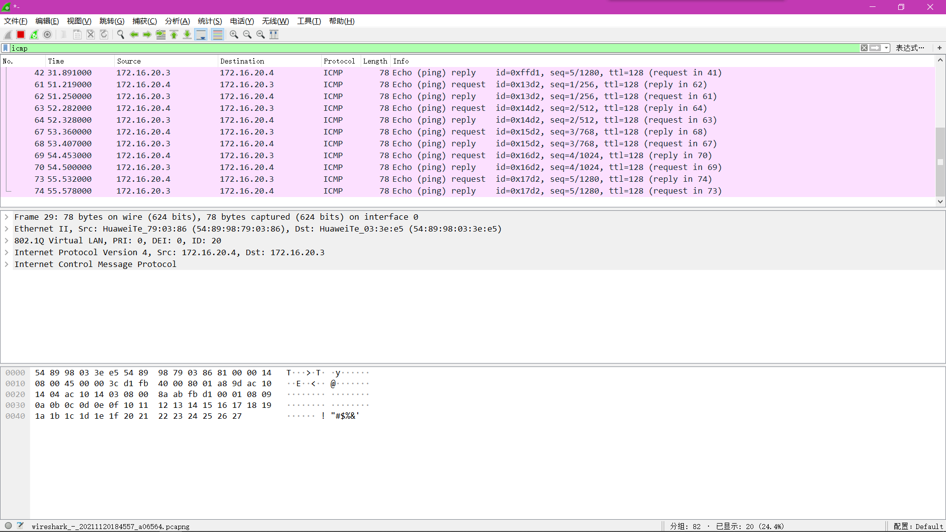
It can be seen that data packets pass through, and the path of PC4 data packets to PC3 is line B, which shows that spanning tree example 2 is successfully applied in this experiment. In order to check the final experimental effect, we then check whether the line from PC2 to PC1 is our ideal A line. Now we start capturing packets at Gigabit Ethernet 0 / 0 / 3 port of SW2.

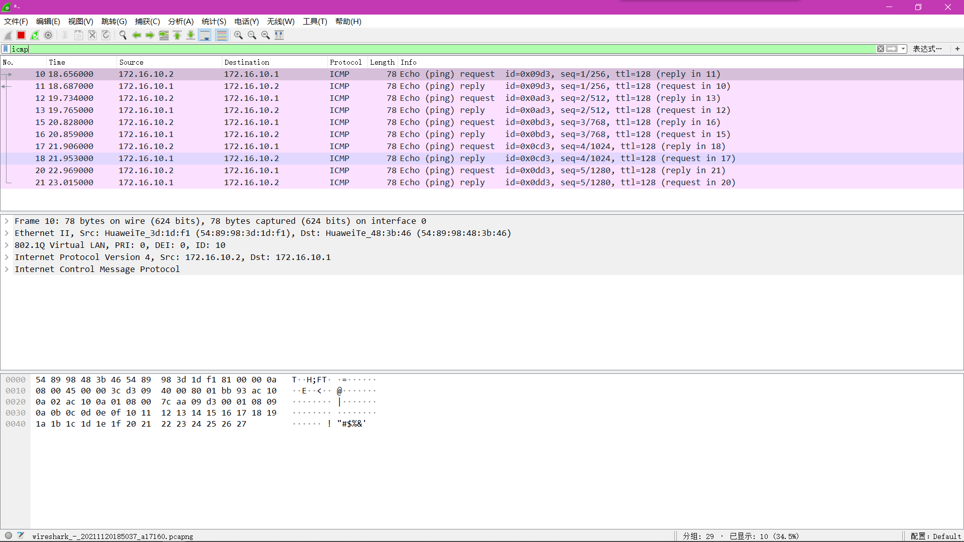
It can be seen that ICMP messages pass, indicating that PC2 accesses PC1 through line A, and example 1 is also successfully applied.