Networking requirements
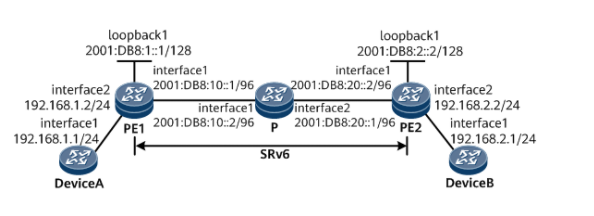
As shown in Figure 1, routers PE1, P and PE2 belong to the same autonomous system, and they are required to achieve the purpose of IPv6 network interconnection through IS-IS protocol. PE1, P and PE2 belong to IS-IS process 1 and are all Level-1 devices. IBGP neighbors are deployed between PE1 and PE2, and EBGP neighbors are deployed between PE and Device.
It is required to establish a two-way SRv6 BE path between PE1 and PE2 to carry the IPv4 service of the public network.
Figure 1 # configuration of public network IPv4 over SRv6 BE networking diagram
Configuration ideas
- Enable the IPv6 forwarding capability of PE1, P and PE2 interfaces, and configure the IPv6 address of each interface.
- Enable IS-IS on PE1, P and PE2, configure Level level and specify network entity.
- Establish EBGP peer relationship between PE and Device.
- Establish MP-IBGP peer relationship between PE S.
- Configure SRv6 on PE1 and PE2. Configure SRv6 capability of IS-IS.
Operation steps
1. Enable the IPv6 forwarding capability of each interface and configure the IPv6 address. Taking PE1 as an example, the configuration process of other routers is the same and will not be repeated
<HUAWEI> system-view
[~HUAWEI] sysname PE1
[*HUAWEI] commit
[~PE1] interface gigabitethernet 1/0/0
[~PE1-GigabitEthernet1/0/0] ipv6 enable
[*PE1-GigabitEthernet1/0/0] ipv6 address 2001:DB8:10::1 96
[*PE1-GigabitEthernet1/0/0] quit
[*PE1] interface loopback1
[*PE1-LoopBack1] ipv6 enable
[*PE1-LoopBack1] ipv6 address 2001:DB8:1::1 128
[*PE1-LoopBack1] commit
[~PE1-LoopBack1] quit
2. Configure IS-IS
#Configure PE1.
[~PE1] isis 1
[*PE1-isis-1] is-level level-1
[*PE1-isis-1] cost-style wide
[*PE1-isis-1] network-entity 10.0000.0000.0001.00
[*PE1-isis-1] ipv6 enable topology ipv6
[*PE1-isis-1] quit
[*PE1] interface gigabitethernet 1/0/0
[*PE1-GigabitEthernet1/0/0] isis ipv6 enable 1
[*PE1-GigabitEthernet1/0/0] quit
[*PE1] interface loopback1
[*PE1-LoopBack1] isis ipv6 enable 1
[*PE1-LoopBack1] commit
[~PE1-LoopBack1] quit
#Configure P.
[~P] isis 1
[*P-isis-1] is-level level-1
[*P-isis-1] cost-style wide
[*P-isis-1] network-entity 10.0000.0000.0002.00
[*P-isis-1] ipv6 enable topology ipv6
[*P-isis-1] quit
[*P] interface gigabitethernet 1/0/0
[*P-GigabitEthernet1/0/0] isis ipv6 enable 1
[*P-GigabitEthernet1/0/0] quit
[*P] interface gigabitethernet 2/0/0
[*P-GigabitEthernet2/0/0] isis ipv6 enable 1
[*P-GigabitEthernet2/0/0] commit
[~P-GigabitEthernet2/0/0] quit
#Configure PE2.
[~PE2] isis 1
[*PE2-isis-1] is-level level-1
[*PE2-isis-1] cost-style wide
[*PE2-isis-1] network-entity 10.0000.0000.0003.00
[*PE2-isis-1] ipv6 enable topology ipv6
[*PE2-isis-1] quit
[*PE2] interface gigabitethernet 1/0/0
[*PE2-GigabitEthernet1/0/0] isis ipv6 enable 1
[*PE2-GigabitEthernet1/0/0] quit
[*PE2] interface loopback1
[*PE2-LoopBack1] isis ipv6 enable 1
[*PE2-LoopBack1] commit
[~PE2-LoopBack1] quit
After the configuration is completed, you can check whether the IS-IS configuration is successful according to the following instructions.
#Displays IS-IS neighbor information. Take PE1 as an example.
[~PE1] display isis peer

                          Peer information for ISIS(1)

  System Id     Interface          Circuit Id        State HoldTime Type     PRI
--------------------------------------------------------------------------------
0000.0000.0002* GE1/0/0            0000.0000.0002.01  Up   8s       L1       64

Total Peer(s): 1
#Displays IS-IS routing table information. Take PE1 as an example.
[~PE1] display isis route
                         Route information for ISIS(1)
                         -----------------------------

                        ISIS(1) Level-1 Forwarding Table
                        --------------------------------

 IPV6 Dest.            ExitInterface      NextHop                    Cost     Flags
--------------------------------------------------------------------------------
2001:DB8:1::1/128      Loop1              Direct                     0        D/-/L/-
2001:DB8:2::2/128      GE1/0/0            FE80::3A92:6CFF:FE21:10    10       A/-/-/-
2001:DB8:10::/96       GE1/0/0            Direct                     10       D/-/L/-
2001:DB8:20::/96       GE1/0/0            FE80::3A92:6CFF:FE21:10    20       A/-/-/-
     Flags: D-Direct, A-Added to URT, L-Advertised in LSPs, S-IGP Shortcut,
            U-Up/Down Bit Set, LP-Local Prefix-Sid
     Protect Type: L-Link Protect, N-Node Protect
Establish peer relationship between Device 3. GP and EB
#Configure DeviceA.
[~DeviceA] interface gigabitethernet 1/0/0
[~DeviceA-GigabitEthernet1/0/0] ip address 192.168.1.1 24
[*DeviceA-GigabitEthernet1/0/0] quit
[*DeviceA] bgp 200
[*DeviceA-bgp] router-id 4.4.4.4
[*DeviceA-bgp] peer 192.168.1.2 as-number 100
[*DeviceA-bgp] quit
[*DeviceA] commit
#Configure PE1.
[~PE1] interface gigabitethernet 2/0/0
[~PE1-GigabitEthernet2/0/0] ip address 192.168.1.2 24
[*PE1-GigabitEthernet2/0/0] quit
[*PE1] bgp 100
[*PE1-bgp] router-id 1.1.1.1
[*PE1-bgp] peer 192.168.1.1 as-number 200
[*PE1-bgp] ipv4-family unicast
[*PE1-bgp-af-ipv4] peer 192.168.1.1 enable
[*PE1-bgp-af-ipv4] network 192.168.1.0 24
[*PE1-bgp-af-ipv4] commit
[~PE1-bgp-af-ipv4] quit
[~PE1-bgp] quit
#Configure DeviceB.
[~DeviceB] interface gigabitethernet 1/0/0
[~DeviceB-GigabitEthernet1/0/0] ip address 192.168.2.1 24
[*DeviceB-GigabitEthernet1/0/0] quit
[*DeviceB] bgp 300
[*DeviceB-bgp] router-id 5.5.5.5
[*DeviceB-bgp] peer 192.168.2.2 as-number 100
[*DeviceB-bgp] quit
[*DeviceB] commit
#Configure PE2.
[~PE2] interface gigabitethernet 2/0/0
[~PE2-GigabitEthernet2/0/0] ip address 192.168.2.2 24
[*PE2-GigabitEthernet2/0/0] quit
[*PE2] bgp 100
[*PE2-bgp] router-id 2.2.2.2
[*PE2-bgp] peer 192.168.2.1 as-number 300
[*PE2-bgp] ipv4-family unicast
[*PE2-bgp-af-ipv4] peer 192.168.2.1 enable
[*PE2-bgp-af-ipv4] network 192.168.2.0 24
[*PE2-bgp-af-ipv4] commit
[~PE2-bgp-af-ipv4] quit
[~PE2-bgp] quit
After the configuration is completed, execute the display bgp peer command on the PE Device. You can see that the BGP peer relationship between PE and Device has been Established and reached the Established state.
Take the peer relationship between PE1 and DeviceA as an example:
4. Establish MP-IBGP peer relationship between PE S
#Configure PE1.
[~PE1] bgp 100
[~PE1-bgp] peer 2001:DB8:2::2 as-number 100
[*PE1-bgp] peer 2001:DB8:2::2 connect-interface loopback1
[*PE1-bgp] ipv4-family unicast
[*PE1-bgp-af-ipv4] peer 2001:DB8:2::2 enable
[*PE1-bgp-af-ipv4] commit
[~PE1-bgp-af-ipv4] quit
[~PE1-bgp] quit
#Configure PE2.
[~PE2] bgp 100
[~PE2-bgp] peer 2001:DB8:1::1 as-number 100
[*PE2-bgp] peer 2001:DB8:1::1 connect-interface loopback1
[*PE2-bgp] ipv4-family unicast
[*PE2-bgp-af-ipv4] peer 2001:DB8:1::1 enable
[*PE2-bgp-af-ipv4] commit
[~PE2-bgp-af-ipv4] quit
[~PE2-bgp] quit
After the configuration is completed, execute the display bgp peer command on the PE device. You can see that the BGP peer relationship between PES has been Established and reached the Established state. Take the display of PE1 as an example:
[~PE1] display bgp peer

 BGP local router ID : 1.1.1.1
 Local AS number : 100
 Total number of peers : 2                 Peers in established state : 2

  Peer            V          AS  MsgRcvd  MsgSent  OutQ  Up/Down       State  PrefRcv
  192.168.1.1     4         200       10       11     0 00:05:15 Established        2
  2001:DB8:2::2   4         100       10       11     0 00:05:15 Established        2
5. Establish SRv6 BE path between PE S
#Configure PE1.
[~PE1] segment-routing ipv6
[*PE1-segment-routing-ipv6] encapsulation source-address 2001:DB8:1::1
[*PE1-segment-routing-ipv6] locator aa ipv6-prefix 2001:DB8:100:: 64 static 32
[*PE1-segment-routing-ipv6-locator] quit
[*PE1-segment-routing-ipv6] quit
[*PE1] isis 1
[*PE1-isis-1] segment-routing ipv6 locator aa
[*PE1-isis-1] commit
[~PE1-isis-1] quit
[~PE1] bgp 100
[~PE1-bgp] ipv4-family unicast
[*PE1-bgp-af-ipv4] peer 2001:DB8:2::2 prefix-sid
[*PE1-bgp-af-ipv4] segment-routing ipv6 best-effort
[*PE1-bgp-af-ipv4] segment-routing ipv6 locator aa
[*PE1-bgp-af-ipv4] commit
[~PE1-bgp-af-ipv4] quit
[~PE1-bgp] quit
#Configure PE2.
[~PE2] segment-routing ipv6
[*PE2-segment-routing-ipv6] encapsulation source-address 2001:DB8:2::2
[*PE2-segment-routing-ipv6] locator aa ipv6-prefix 2001:DB8:200:: 64 static 32
[*PE2-segment-routing-ipv6-locator] quit
[*PE2-segment-routing-ipv6] quit
[*PE2] isis 1
[*PE2-isis-1] segment-routing ipv6 locator aa
[*PE2-isis-1] commit
[~PE2-isis-1] quit
[~PE2] bgp 100
[~PE2-bgp] ipv4-family unicast
[*PE2-bgp-af-ipv4] peer 2001:DB8:1::1 prefix-sid
[*PE2-bgp-af-ipv4] segment-routing ipv6 best-effort
[*PE2-bgp-af-ipv4] segment-routing ipv6 locator aa
[*PE2-bgp-af-ipv4] commit
[~PE2-bgp-af-ipv4] quit
[~PE2-bgp] quit
6. Check the configuration results
Execute the display segment routing IPv6 Local SID end DT4 forwarding command to view the Local SID table information of SRv6. Take PE1 as an example:
[~PE1] display segment-routing ipv6 local-sid end-dt4 forwarding
                    My Local-SID End.DT4 Forwarding Table
                    -------------------------------------

SID        : 2001:DB8:100::1:0:1/128                 FuncType : End.DT4
VPN Name   : _public_                                VPN ID   : 0
LocatorName: aa                                      LocatorID: 1

Total SID(s): 1
Execute the display BGP routing table command to see the BGP routing table information. Take the display of PE2 as an example:
[~PE2] display bgp routing-table 192.168.1.0

 BGP local router ID : 2.2.2.2
 Local AS number : 100
 Paths:   1 available, 1 best, 1 select, 0 best-external, 0 add-path
 BGP routing table entry information of 192.168.1.0/24:
 From: 2001:DB8:1::1 (1.1.1.1)
 Route Duration: 2d02h11m33s
 Relay IP Nexthop: FE80::3ABD:6CFF:FE31:300
 Relay IP Out-Interface: GigabitEthernet1/0/0
 Original nexthop: 2001:DB8:1::1
 Qos information : 0x0
 Prefix-sid: 2001:DB8:100::1:0:1
 AS-path Nil, origin igp, MED 0, localpref 100, pref-val 0, valid, internal, best, select, pre 255, IGP cost 20
 Advertised to such 1 peers:
    192.168.2.1
Device s can Ping each other, for example:
[~DeviceA] ping 192.168.2.1
  PING 192.168.2.1: 56  data bytes, press CTRL_C to break
    Reply from 192.168.2.1: bytes=56 Sequence=1 ttl=253 time=7 ms
    Reply from 192.168.2.1: bytes=56 Sequence=2 ttl=253 time=5 ms
    Reply from 192.168.2.1: bytes=56 Sequence=3 ttl=253 time=4 ms
    Reply from 192.168.2.1: bytes=56 Sequence=4 ttl=253 time=5 ms
    Reply from 192.168.2.1: bytes=56 Sequence=5 ttl=253 time=5 ms

  --- 192.168.2.1 ping statistics ---
    5 packet(s) transmitted
    5 packet(s) received
    0.00% packet loss
    round-trip min/avg/max = 4/5/7 ms