1, Interrupt system
The interrupt system mainly has the following key points:
1. Interrupt vector table (find the corresponding interrupt service function entry address through address offset)
2. Interrupt controller (STM32 uses NVIC interrupt controller and iMX6ULL uses GIC interrupt controller)
3. Interrupt enable (global interrupt enable and specified interrupt enable)
4. Interrupt service function
Note: pay attention to configuring the start address of interrupt vector table (that is, the link start address. iMX6ULL needs to configure VBAR register (vector table base address register) and read CBAR register (GIC base address, which is a read-only register) through coprocessor)
2, Cortex-A7 interrupt system
See B1 in ARM Architecture Reference Manual ARMv7-A and ARMv7-R edition for details 8. Exception handling and B1 9 exception descriptions.
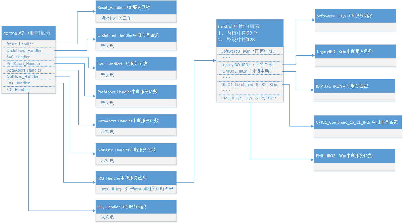
1. Interrupt vector table
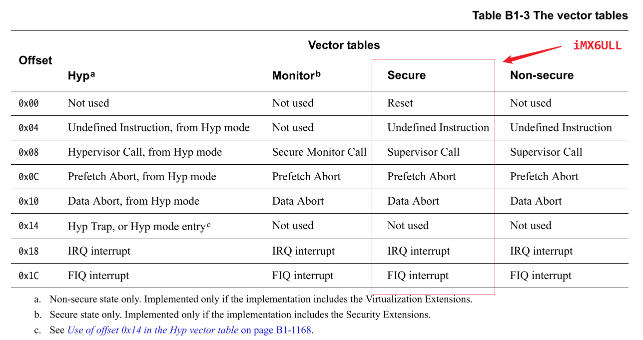
- Rest - reset interrupt: after the CPU is reset, it will enter the reset interrupt. We can do some initialization work in the reset interrupt service function, such as initializing SP pointer, DDR, etc.
- Undefined Instruction - Undefined Instruction interrupt: this interrupt occurs if the instruction is not recognized.
- Software Interrupt - soft interrupt: the interrupt caused by SWI instruction. The system call of Linux will use SWI instruction to cause soft interrupt and fall into kernel space through soft interrupt.
- Prefetch Abort - instruction Prefetch Abort interrupt: this interrupt occurs when an error occurs in prefetch instructions.
- Data Abort - data access abort interrupt: this interrupt occurs when there is an error accessing data.
- IRQ Interrupt - external interrupt: external device interrupts inside the chip will cause this interrupt to occur.
- FIQ Interrupt - fast interrupt: you can use this interrupt if you need to process the interrupt quickly.
The interrupt vector table contains the entry address of the interrupt service function. As can be seen from the above figure, Cortex-A7 has a total of 8 interrupts, and one interrupt vector is not used. In fact, there are only 7 interrupts.
There are 128 interrupts in iMX6ULL. How can the seven interrupt vector tables manage 128 interrupts?
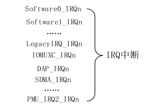
The figure above shows Cortex-A7 interrupt management. All peripheral interrupts trigger IRQ interrupts.
2. Interrupt controller
For details, see: GICv2 finishing_ OnlyLove_ Blog - CSDN blog
3. Interrupt enable
1. IRQ and FIQ total interrupt enable
IRQ is disabled when I=1 of register CPSR, and IRQ is enabled when I=0; F=1 disable FIQ, F=0 enable FIQ.
2. Peripheral interrupt enable
GIC register GICD_ISENABLERn and GICD_ ICENABLERn is used to enable and disable external interrupts. A bit controls the enabling of an interrupt ID.
3. Interrupt priority setting
GICC_ The PMR register configures the interrupt priority.
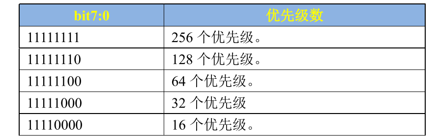
i.MX6ULL is a Cortex-A7 kernel, so it supports 32 priorities, so GICC_PMR should be set to 0b11111000.
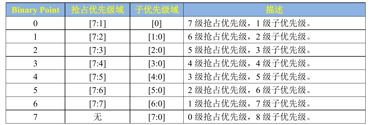
GICC_BPR register is used to configure how many bits preemptive priority and sub priority occupy respectively. GICC_ The BPR structure is shown in the following figure:
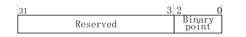
Register GICC_ Only the lower 3 bits of BPR are valid. With different values, the bits occupied by preemption priority and sub priority are also different. The configuration is shown in the following figure:
4. Interrupt service function
See code implementation for details.
3, Code implementation
1. Design idea of interrupt implementation
2. Engineering establishment
1. Engineering configuration
Develop in vscode and configure according to the relevant rules of vscode.
Open VSCode, press "Crtl+Shift+P" to open the console of VSCode, and then enter "C/C++: Edit configurations(JSON)" to open the C/C + + edit configuration file.
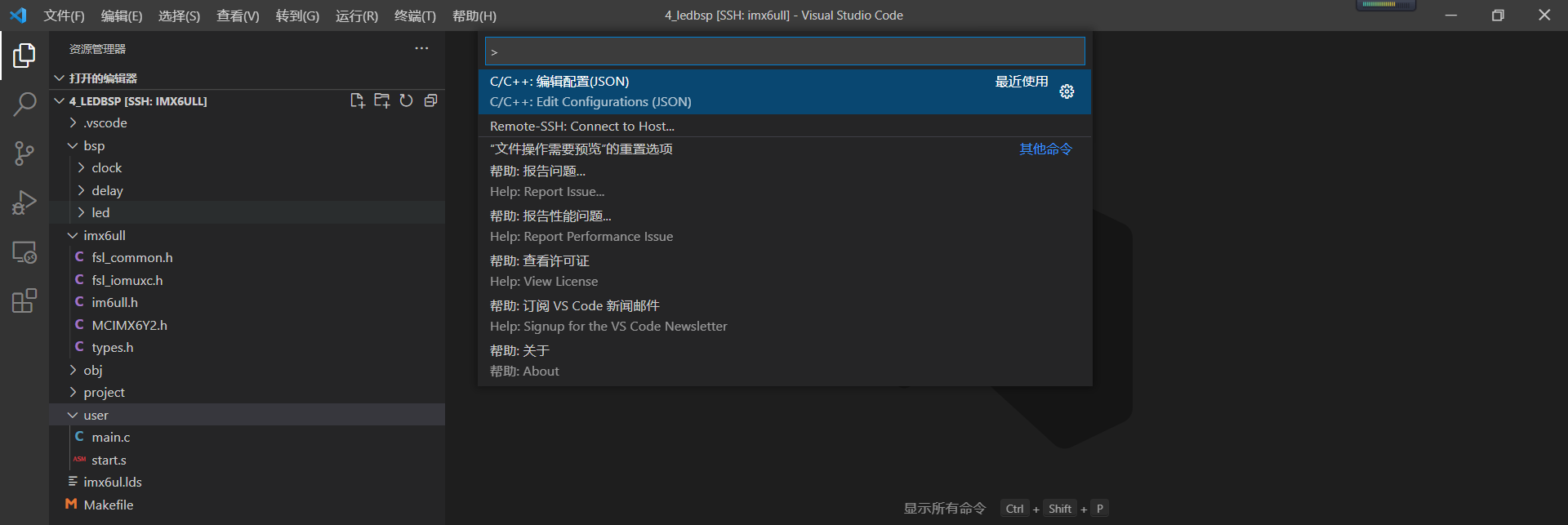
After opening, it will be automatically displayed in the Generate a file named C under the vscode directory_ cpp_ properties. JSON. The default content of this file is as follows:
{
    "configurations": [
        {
            "name": "Linux",
            "includePath": [
                "${workspaceFolder}/**"
            ],
            "defines": [],
            "compilerPath": "/usr/bin/gcc",
            "cStandard": "gnu17",
            "cppStandard": "gnu++14",
            "intelliSenseMode": "linux-gcc-x64"
        }
    ],
    "version": 4
}
includePath indicates the path of the header file. You need to list the directories containing the header file. Revised c_cpp_properties.json file contents are as follows:
{
    "configurations": [
        {
            "name": "Linux",
            "includePath": [
                "${workspaceFolder}/**",
                "${workspaceFolder}/imx6ull/inc",	/* Library functions implemented for imx6ull */
                "${workspaceFolder}/user",			/* Start file start S and main c */
                "${workspaceFolder}/bsp/clock",		/* Clock configuration */
                "${workspaceFolder}/bsp/delay",		/* Delay Functions  */
                "${workspaceFolder}/bsp/led",		/* led Lamp correlation function */
                "${workspaceFolder}/bsp/key"		/* Key correlation function */
            ],
            "defines": [],
            "compilerPath": "/usr/bin/gcc",
            "cStandard": "gnu17",
            "cppStandard": "gnu++14",
            "intelliSenseMode": "linux-gcc-x64"
        }
    ],
    "version": 4
}
2,makefile
CROSS_COMPILE	?= arm-linux-gnueabihf-
TARGET			?= int

CC				:= $(CROSS_COMPILE)gcc
LD				:= $(CROSS_COMPILE)ld
OBJCOPY			:= $(CROSS_COMPILE)objcopy
OBJDUMP			:= $(CROSS_COMPILE)objdump

INCDIRS			:= imx6ull/inc \
				   bsp/clock \
				   bsp/delay \
				   bsp/led \
				   bsp/key \
				   bsp/int \
				   user

SRCDIRS			:= imx6ull/src \
				   bsp/clock \
				   bsp/delay \
				   bsp/led \
				   bsp/key \
				   bsp/int \
				   user

INCLUDE			:= $(patsubst %, -I %, $(INCDIRS))

SFILES			:= $(foreach dir, $(SRCDIRS), $(wildcard $(dir)/*.s))
CFILES			:= $(foreach dir, $(SRCDIRS), $(wildcard $(dir)/*.c))

SFILENDIR		:= $(notdir $(SFILES))
CFILENDIR		:= $(notdir $(CFILES))

SOBJS			:= $(patsubst %, obj/%, $(SFILENDIR:.s=.o))
COBJS			:= $(patsubst %, obj/%, $(CFILENDIR:.c=.o))
OBJS			:= $(SOBJS) $(COBJS)

VPATH			:= $(SRCDIRS)

.PHONY: clean

$(TARGET).bin : $(OBJS)
	$(LD) -Timx6ul.lds -o $(TARGET).elf $^
	$(OBJCOPY) -O binary -S $(TARGET).elf $@
	$(OBJDUMP) -D -m arm $(TARGET).elf > $(TARGET).dis

$(SOBJS) : obj/%.o : %.s
	$(CC) -Wall -nostdlib -c -O2 $(INCLUDE) -o $@ $<

$(COBJS) : obj/%.o : %.c
	$(CC) -Wall -nostdlib -c -O2 $(INCLUDE) -o $@ $<

clean:
	rm -rf $(TARGET).elf $(TARGET).dis $(TARGET).bin $(COBJS) $(SOBJS)
3. Add interrupt vector table
Add interrupt vector table to implement only the basic architecture. The code is implemented in start S, the specific code is as follows:
.global __start /* Global label */

/*
 * Description: 	_ The start function first interrupts the creation of the vector table
 * Reference document: ARM Cortex-A(armV7) programming manual v4 0.pdf p42, 3 ARM Processor Modes and Registers
 * 		 	ARM Cortex-A(armV7)Programming manual v4 0.pdf P165 11.1.1 exception priorities
 */
_start:
	ldr pc, =Reset_Handler		/* Reset interrupt 					*/
	ldr pc, =Undefined_Handler	/* Undefined interrupt 					*/
	ldr pc, =SVC_Handler		/* SVC(Supervisor)interrupt 		*/
	ldr pc, =PrefAbort_Handler	/* Prefetch termination interrupt 					*/
	ldr pc, =DataAbort_Handler	/* Data termination interrupt 					*/
	ldr	pc, =NotUsed_Handler	/* Unused interrupt					*/
	ldr pc, =IRQ_Handler		/* IRQ interrupt 					*/
	ldr pc, =FIQ_Handler		/* FIQ(Fast interrupt) undefined interrupt 			*/

Reset_Handler:
    ldr r0, =Reset_Handler
    bx r0

Undefined_Handler:
    ldr r0, =Undefined_Handler
    bx r0

SVC_Handler:
    ldr r0, =SVC_Handler
    bx r0

PrefAbort_Handler:
    ldr r0, =PrefAbort_Handler
    bx r0

DataAbort_Handler:
    ldr r0, =DataAbort_Handler
    bx r0

NotUsed_Handler:
    ldr r0, =NotUsed_Handler
    bx r0

IRQ_Handler:
    ldr r0, =IRQ_Handler
    bx r0

FIQ_Handler:
    ldr r0, =FIQ_Handler
    bx r0
Compile the test, and the compilation log is as follows:
onlylove@ubuntu:~/linux/driver/board_driver/6_int$ make
arm-linux-gnueabihf-gcc -Wall -nostdlib -c -O2  -I imx6ull/inc  -I bsp/clock  -I bsp/delay  -I bsp/led  -I bsp/key  -I bsp/int  -I user -o obj/start.o user/start.s
user/start.s: Assembler messages:
user/start.s: Warning: end of file not at end of a line; newline inserted
arm-linux-gnueabihf-gcc -Wall -nostdlib -c -O2  -I imx6ull/inc  -I bsp/clock  -I bsp/delay  -I bsp/led  -I bsp/key  -I bsp/int  -I user -o obj/imx6ull_gpio.o imx6ull/src/imx6ull_gpio.c
arm-linux-gnueabihf-gcc -Wall -nostdlib -c -O2  -I imx6ull/inc  -I bsp/clock  -I bsp/delay  -I bsp/led  -I bsp/key  -I bsp/int  -I user -o obj/clock.o bsp/clock/clock.c
arm-linux-gnueabihf-gcc -Wall -nostdlib -c -O2  -I imx6ull/inc  -I bsp/clock  -I bsp/delay  -I bsp/led  -I bsp/key  -I bsp/int  -I user -o obj/delay.o bsp/delay/delay.c
arm-linux-gnueabihf-gcc -Wall -nostdlib -c -O2  -I imx6ull/inc  -I bsp/clock  -I bsp/delay  -I bsp/led  -I bsp/key  -I bsp/int  -I user -o obj/led.o bsp/led/led.c
arm-linux-gnueabihf-gcc -Wall -nostdlib -c -O2  -I imx6ull/inc  -I bsp/clock  -I bsp/delay  -I bsp/led  -I bsp/key  -I bsp/int  -I user -o obj/key.o bsp/key/key.c
arm-linux-gnueabihf-gcc -Wall -nostdlib -c -O2  -I imx6ull/inc  -I bsp/clock  -I bsp/delay  -I bsp/led  -I bsp/key  -I bsp/int  -I user -o obj/main.o user/main.c
arm-linux-gnueabihf-ld -Timx6ul.lds -o int.elf obj/start.o obj/imx6ull_gpio.o obj/clock.o obj/delay.o obj/led.o obj/key.o obj/main.o
arm-linux-gnueabihf-objcopy -O binary -S int.elf int.bin
arm-linux-gnueabihf-objdump -D -m arm int.elf > int.dis
onlylove@ubuntu:~/linux/driver/board_driver/6_int$
View the compilation results through the disassembly file:
int.elf:     file format elf32-littlearm


Disassembly of section .text:

87800000 <_start>:
87800000:	e59ff058 	ldr	pc, [pc, #88]	; 87800060 <FIQ_Handler+0x8>
87800004:	e59ff058 	ldr	pc, [pc, #88]	; 87800064 <FIQ_Handler+0xc>
87800008:	e59ff058 	ldr	pc, [pc, #88]	; 87800068 <FIQ_Handler+0x10>
8780000c:	e59ff058 	ldr	pc, [pc, #88]	; 8780006c <FIQ_Handler+0x14>
87800010:	e59ff058 	ldr	pc, [pc, #88]	; 87800070 <FIQ_Handler+0x18>
87800014:	e59ff058 	ldr	pc, [pc, #88]	; 87800074 <FIQ_Handler+0x1c>
87800018:	e59ff058 	ldr	pc, [pc, #88]	; 87800078 <FIQ_Handler+0x20>
8780001c:	e59ff058 	ldr	pc, [pc, #88]	; 8780007c <FIQ_Handler+0x24>

87800020 <Reset_Handler>:
87800020:	e59f0038 	ldr	r0, [pc, #56]	; 87800060 <FIQ_Handler+0x8>
87800024:	e12fff10 	bx	r0

87800028 <Undefined_Handler>:
87800028:	e59f0034 	ldr	r0, [pc, #52]	; 87800064 <FIQ_Handler+0xc>
8780002c:	e12fff10 	bx	r0

87800030 <SVC_Handler>:
87800030:	e59f0030 	ldr	r0, [pc, #48]	; 87800068 <FIQ_Handler+0x10>
87800034:	e12fff10 	bx	r0

87800038 <PrefAbort_Handler>:
87800038:	e59f002c 	ldr	r0, [pc, #44]	; 8780006c <FIQ_Handler+0x14>
8780003c:	e12fff10 	bx	r0

87800040 <DataAbort_Handler>:
87800040:	e59f0028 	ldr	r0, [pc, #40]	; 87800070 <FIQ_Handler+0x18>
87800044:	e12fff10 	bx	r0

87800048 <NotUsed_Handler>:
87800048:	e59f0024 	ldr	r0, [pc, #36]	; 87800074 <FIQ_Handler+0x1c>
8780004c:	e12fff10 	bx	r0

87800050 <IRQ_Handler>:
87800050:	e59f0020 	ldr	r0, [pc, #32]	; 87800078 <FIQ_Handler+0x20>
87800054:	e12fff10 	bx	r0

87800058 <FIQ_Handler>:
87800058:	e59f001c 	ldr	r0, [pc, #28]	; 8780007c <FIQ_Handler+0x24>
8780005c:	e12fff10 	bx	r0

......
4. Add interrupt service function
1. Add reset interrupt service function
Reset interrupt service function is the first function to execute after reset. It mainly completes some initialization functions before system operation. The specific functions include:
- Turn off global interrupt
- Close ICache, DCache
- Turn off MMU
- Set interrupt vector table base register (VBAR)
- Set stack pointer in each mode
- Turn on global interrupt
- Enable IRQ interrupt
- Jump to main function
/* Reset interrupt */
Reset_Handler:

	cpsid i						/* Turn off global interrupt */

	/* Turn off I,DCache and MMU
	 * Adopt a read change write approach.
	 */
	mrc     p15, 0, r0, c1, c0, 0     /* Read the C1 register of CP15 into R0       		        	*/
    bic     r0,  r0, #(0x1 < < 12) / * clear bit12 bit (I bit) of C1 register and close I Cache 	*/
    bic     r0,  r0, #(0x1 < < 2) / * clear bit2(C bit) of C1 register and close D Cache 				*/
    bic     r0,  r0, #0x2 / * clear Bit1 (bit a) of C1 register and turn off alignment 						*/
    bic     r0,  r0, #(0x1 < < 11) / * clear bit11(Z bit) of C1 register and turn off branch prediction 					*/
    bic     r0,  r0, #0x1 / * clear bit0(M bit) of C1 register and turn off MMU 				       	*/
    mcr     p15, 0, r0, c1, c0, 0     /* Write the value in r0 register to C1 register of CP15	 				*/

	/* Assembly version setting interrupt vector table offset */
	ldr r0, =0X87800000

	dsb
	isb
	mcr p15, 0, r0, c12, c0, 0
	dsb
	isb

	/* Set the stack pointer in each mode,
	 * Note: the stack of IMX6UL grows downward!
	 * Stack pointer address must be aligned with 4-byte address!!!
	 * DDR Range: 0x80000000 ~ 0x9fffff
	 */
	/* Enter IRQ mode */
	mrs r0, cpsr
	bic r0, r0, #0x1f  	/*  Clear the lower 5 bits in r0 register, that is, M0~M4 of cpsr 	*/
	orr r0, r0, #0x12  	/*  r0 or 0x13 above indicates that IRQ mode is used 					*/
	msr cpsr, r0		/* Write the data of r0 to cpsr_c medium 					*/
	ldr sp, =0x80600000	/* Set the stack head address in IRQ mode to 0X80600000 and the size to 2MB */

	/* Enter SYS mode */
	mrs r0, cpsr
	bic r0, r0, #0x1f  	/*  Clear the lower 5 bits in r0 register, that is, M0~M4 of cpsr 	*/
	orr r0, r0, #0x1f  	/*  r0 or 0x13 above indicates that SYS mode is used 					*/
	msr cpsr, r0		/* Write the data of r0 to cpsr_c medium 					*/
	ldr sp, =0x80400000	/* Set the stack head address in SYS mode to 0X80400000 and the size to 2MB */

	/* Enter SVC mode */
	mrs r0, cpsr
	bic r0, r0, #0x1f  	/*  Clear the lower 5 bits in r0 register, that is, M0~M4 of cpsr 	*/
	orr r0, r0, #0x13  	/*  r0 or 0x13 above indicates that SVC mode is used 					*/
	msr cpsr, r0		/* Write the data of r0 to cpsr_c medium 					*/
	ldr sp, =0X80200000	/* Set the stack head address in SVC mode to 0X80200000 and the size to 2MB */

	cpsie i				/* Turn on global interrupt */

	/* Enable IRQ interrupt */
	mrs r0, cpsr		/* Read the value of cpsr register into r0 			*/
	bic r0, r0, #0x80 	/*  Clearing bit7 in r0 register, i.e. I bit in CPSR, indicates that IRQ interrupt is allowed*/
	msr cpsr, r0		/* Re write r0 to cpsr 			*/

	b main				/* Jump to main function 			 	*/
The above source code is copied from the punctual atomic routine, and there is no problem in the verification test on the development board.
2. Add IRQ interrupt service function
IRQ interrupt service function is mainly used to process imx6ull peripheral interrupts. The processing logic is as follows:
- Protect the field (including general registers (r0~r3, r12) and status registers (spsr)
- Read GIC base address
- Get interrupt ID number (GICC_IAR.Interrupt ID)
- Set SVC mode to allow another interrupt
- Call imx6ull_ The IRQ function handles the corresponding peripheral interrupt
- Enter IRQ mode and wait for interrupt processing to complete
- Write EOIR after interrupt execution
- Restore site
	push {lr}					/* Save lr address */
	push {r0-r3, r12}			/* Save r0-r3, r12 registers */

	mrs r0, spsr				/* Read spsr register */
	push {r0}					/* Save spsr register */

	mrc p15, 4, r1, c15, c0, 0 /* From the value in C0 register of CP15 to R1 register
								* Refer to the document ARM Cortex-A(armV7) programming manual v4 0.pdf P49
								* Cortex-A7 Technical ReferenceManua.pdf P68 P138
								*/
	add r1, r1, #0X2000 			/*  The base address of GIC plus 0x2000 is the base address of the CPU interface of GIC*/
	ldr r0, [r1, #0XC] 			/*  The base address of the CPU interface end of GIC plus 0X0C is GICC_IAR register,
								 * GICC_IAR The register stores the interrupt number of the current interrupt. We need to
								 * This interrupt number is used to absolutely call which interrupt service function
								 */
	push {r0, r1}				/* Save r0,r1 */

	cps #0x13 					/*  Enter SVC mode and allow other interrupts to enter again*/

	push {lr}					/* The lr register that holds the SVC mode */
	ldr r2, =imx6ull_irq	    /* Load the C language interrupt handling function into the r2 register*/
	blx r2						/* Run the C language interrupt processing function with a parameter, which is saved in the R0 register */

	pop {lr}					/* After executing the C language interrupt service function, lr get out of the stack */
	cps #0x12 					/*  Enter IRQ mode*/
	pop {r0, r1}
	str r0, [r1, #0X10] 			/*  Interrupt execution completed, write EOIR*/

	pop {r0}
	msr spsr_cxsf, r0			/* Restore spsr */

	pop {r0-r3, r12}			/* r0-r3,r12 Out of stack */
	pop {lr}					/* lr Out of stack */
	subs pc, lr, #four 				/*  Assign lr-4 to pc*/
3. Migrate interrupt related files in SDK package
Main transplant core_ca7.h file, which is saved in the i.MX6ULL-SDK\CORTEXA\Include directory.
Note: file migration is provided on time.
4. Interrupt initialization related processing
1. Call GIC provided by SDK_ Init() to initialize GIC.
2. Initialize the imx6ull interrupt vector table and set each item of the imx6ull interrupt vector table as the default interrupt processing (function logic: dead loop).
3. Set the start address of the interrupt vector table as needed.
#include "imx6ull.h"
#include "int.h"

/* Interrupt nested counter */
static unsigned int irqNesting;

/* Interrupt service function table */
static imx6ull_irq_handle_t irqTable[NUMBER_OF_INT_VECTORS];

/*
 * @description			: Default interrupt service function
 * @param - giccIar		: interrupt number
 * @param - usrParam	: Interrupt service handler function parameters
 * @return 				: nothing
 */
void im6ull_default_irqhandler(unsigned int giccIar, void *userParam)
{
	while(1)
  	{
   	}
}

/*
 * @description			: Registers the interrupt service function for the specified interrupt number
 * @param - irq			: Interrupt number to register
 * @param - handler		: Interrupt handler to register
 * @param - usrParam	: Interrupt service handler function parameters
 * @return 				: nothing
 */
void imx6ull_register_irqhandler(IRQn_Type irq, imx6ull_irq_handler_t handler, void *userParam)
{
	irqTable[irq].irqHandler = handler;
  	irqTable[irq].userParam = userParam;
}

/*
 * @description	: Initialize interrupt service function table
 * @param		: nothing
 * @return 		: nothing
 */
void im6ull_irq_table_init(void)
{
    unsigned int i = 0;
	irqNesting = 0;

	/* First set all interrupt service functions to default values */
	for(i = 0; i < NUMBER_OF_INT_VECTORS; i++)
	{
		imx6ull_register_irqhandler((IRQn_Type)i,im6ull_default_irqhandler, NULL);
	}
}

/*
 * @description	: Interrupt initialization function
 * @param		: nothing
 * @return 		: nothing
 */
void int_init(void)
{
    GIC_Init();     /* Initialize GIC */
    im6ull_irq_table_init();    /* Initialize interrupt table */
    __set_VBAR((uint32_t)0x87800000);   /* Configure the starting address of interrupt vector table */
}

/*
 * @description			: C Language interrupt service function, irq assembly interrupt service function will
 						  Call this function by looking up in the interrupt service list
 						  Find the interrupt processing function corresponding to the specified interrupt number and execute it.
 * @param - giccIar		: interrupt number
 * @return 				: nothing
 */
void imx6ull_irq(unsigned int giccIar)
{

   uint32_t intNum = giccIar & 0x3FFUL;

   /* Check whether the interrupt number meets the requirements */
   if ((intNum == 1023) || (intNum >= NUMBER_OF_INT_VECTORS))
   {
	 	return;
   }

   irqNesting++;	/* Interrupt nested counter plus one */

   /* Call the determined interrupt service function in irqTable according to the incoming interrupt number.*/
   irqTable[intNum].irqHandler(intNum, irqTable[intNum].userParam);

   irqNesting--;	/* When the interrupt execution is completed, the interrupt nested register is decremented by one */

}
5. GPIO interrupt settings
1. Set interrupt trigger mode
For key interrupt experiment, that is to set GPIO_ICR1 or GPIO_ICR2 register. Detailed description and specific triggering methods include:
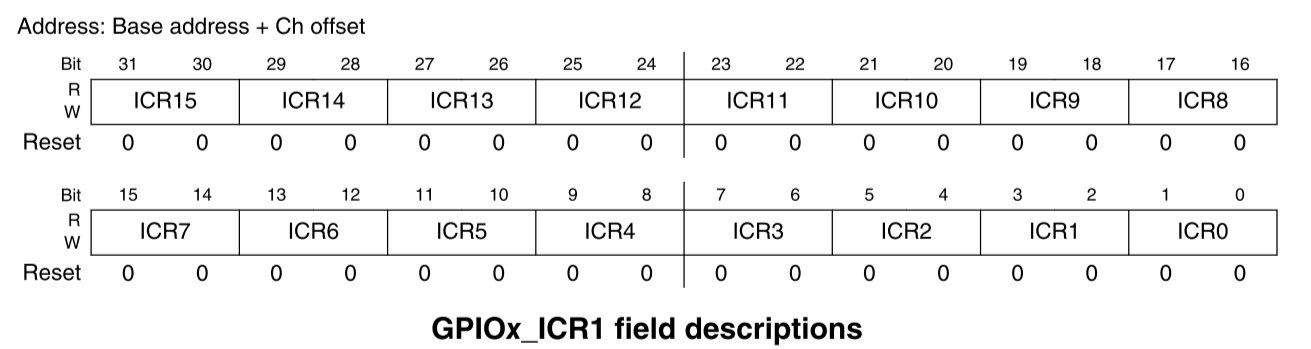
- 00: low level
- 01: high level
- 10: Rising edge
- 11: Falling edge
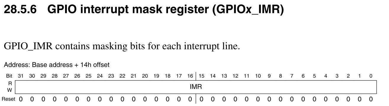
2. GPIO interrupt development and shutdown
By setting gpiox_ The IMR is interrupted on or off.
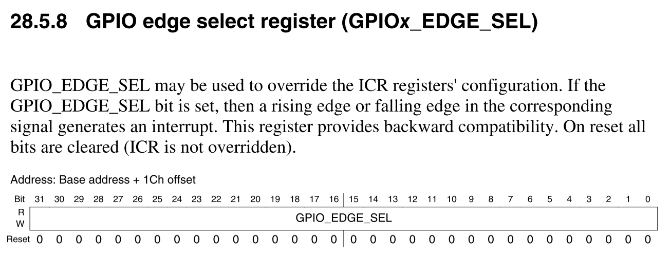
3. GPIO edge select register
GPIO_EDGE_SEL can be used to override the configuration of the ICR register. If GPIO is set_ EDGE_ SEL bit, the rising or falling edge of the corresponding signal will generate an interrupt. When reset, all bits are cleared (ICR will not be overwritten).
4. Interrupt status register
GPIO_ISR is used as an interrupt status indicator. Each bit indicates whether the interrupt condition of the corresponding input signal is met. When the interrupt condition (determined by the corresponding interrupt condition register field) is met, the corresponding bit in this register will be set. Two wait states are required in synchronous read access. Reset requires a wait state.
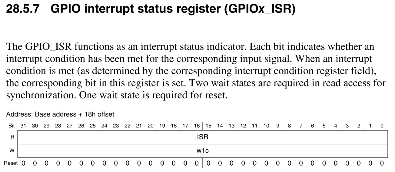
If an interrupt is detected, the corresponding bit will be set to 1. GPIOx_ISR is set to 1, regardless of whether the interrupt is turned on (regardless of the GPIO_IMR register status). When an active interrupt condition is detected, the corresponding bit will remain set until the software clears. Clear the status flag by writing 1 to the corresponding bit position.
5. Schematic analysis
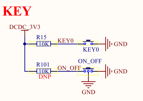
According to the schematic analysis, KEY0 is low level when the key is pressed and high level when the key is released. Through the schematic diagram, it can be determined that KEY0 is connected to UART1_CTS pin.
6. Code implementation
1,imx6ull_gpio.h
#ifndef __IMX6ULL_GPIO_H__
#define __IMX6ULL_GPIO_H__

#include "imx6ull.h"

/*
 * GPIO Input / output enumeration configuration
 */
typedef enum{
    GPIO_INPUT = 0,     /* input */
    GPIO_OUTPUT = 1     /* output */
}gpio_pin_direction_t;

/*
 * GPIO Interrupt trigger type enumeration
 */
typedef enum _gpio_interrupt_mode
{
    kGPIO_NoIntmode = 0U, 				/* Non disruptive function */
    kGPIO_IntLowLevel = 1U, 			/* Low level trigger	*/
    kGPIO_IntHighLevel = 2U, 			/* High level trigger */
    kGPIO_IntRisingEdge = 3U, 			/* Rising edge trigger	*/
    kGPIO_IntFallingEdge = 4U, 			/* Falling edge trigger */
    kGPIO_IntRisingOrFallingEdge = 5U, 	/* Both rising and falling edges are triggered */
} gpio_interrupt_mode_t;

/*
 * GPIO Configuration structure
 */
typedef struct{
    gpio_pin_direction_t direction;         /* GPIO Direction: input or output */
    uint8_t output_logic;                   /* If it is output, the default output level */
    gpio_interrupt_mode_t interruptMode;    /* Interrupt mode */
}gpio_pin_config_t;

int gpio_pinread(GPIO_Type *base, int pin);
void gpio_pinwrite(GPIO_Type *base, int pin, int value);
void gpio_init(GPIO_Type *base, int pin, gpio_pin_config_t *config);


void gpio_intconfig(GPIO_Type* base, unsigned int pin, gpio_interrupt_mode_t pin_int_mode);
void gpio_enableint(GPIO_Type* base, unsigned int pin);
void gpio_disableint(GPIO_Type* base, unsigned int pin);
void gpio_clearintflags(GPIO_Type* base, unsigned int pin);

#endif
2,imx6ull_gpio.c
#include "imx6ull_gpio.h"

/*
 * @description	    : Reads the level value of the specified GPIO.
 * @param - base	: GPIO group to read.
 * @param - pin	    : GPIO pin number to read.
 * @return 		    : nothing
 */
 int gpio_pinread(GPIO_Type *base, int pin)
 {
	 return (((base->DR) >> pin) & 0x1);
 }

/*
 * @description	 : Specifies whether the GPIO output is high or low.
 * @param - base	 : GPIO group to output.
 * @param - pin	 : GPIO pin number to output.
 * @param - value	 : The level to be output, 1 outputs high level and 0 outputs low level
 * @return 		 : nothing
 */
void gpio_pinwrite(GPIO_Type *base, int pin, int value)
{
	 if (value == 0U)
	 {
		 base->DR &= ~(1U << pin); /* Output low level */
	 }
	 else
	 {
		 base->DR |= (1U << pin); /* Output high level */
	 }
}

/*
 * @description		: GPIO initialization.
 * @param - base	: GPIO group to initialize.
 * @param - pin		: To initialize the GPIO pin.
 * @param - config	: GPIO Configure the structure.
 * @return 			: nothing
 */
void gpio_init(GPIO_Type *base, int pin, gpio_pin_config_t *config)
{
    base->IMR &= ~(1U << pin);
    if(config->direction == GPIO_INPUT){                /* GPIO As input */
        base->GDIR &= ~( 1 << pin);
    }else if(config->direction == GPIO_OUTPUT){          /* GPIO As output */
        base->GDIR |= 1 << pin;
        gpio_pinwrite(base,pin, config->output_logic);   /* Set default output level */
    }
	gpio_intconfig(base, pin, config->interruptMode);	/* Interrupt function configuration */
}


/*
 * @description  			: Set the interrupt configuration function of GPIO
 * @param - base 			: GPIO group of the IO to be configured.
 * @param - pin  			: GPIO pin number to configure.
 * @param - pinInterruptMode: Interrupt mode, refer to enumeration type gpio_interrupt_mode_t
 * @return		 			: nothing
 */
void gpio_intconfig(GPIO_Type* base, unsigned int pin, gpio_interrupt_mode_t pin_int_mode)
{
	volatile uint32_t *icr;
	uint32_t icrShift;

	icrShift = pin;

	base->EDGE_SEL &= ~(1U << pin);

	if(pin < 16) 	/* Lower 16 bits */
	{
		icr = &(base->ICR1);
	}
	else			/* High 16 bits */
	{
		icr = &(base->ICR2);
		icrShift -= 16;
	}
	switch(pin_int_mode)
	{
		case(kGPIO_IntLowLevel):
			*icr &= ~(3U << (2 * icrShift));
			break;
		case(kGPIO_IntHighLevel):
			*icr = (*icr & (~(3U << (2 * icrShift)))) | (1U << (2 * icrShift));
			break;
		case(kGPIO_IntRisingEdge):
			*icr = (*icr & (~(3U << (2 * icrShift)))) | (2U << (2 * icrShift));
			break;
		case(kGPIO_IntFallingEdge):
			*icr |= (3U << (2 * icrShift));
			break;
		case(kGPIO_IntRisingOrFallingEdge):
			base->EDGE_SEL |= (1U << pin);
			break;
		default:
			break;
	}
}

/*
 * @description  			: Enable interrupt function of GPIO
 * @param - base 			: The GPIO group in which the IO to be enabled resides.
 * @param - pin  			: The number of GPIO to enable within the group.
 * @return		 			: nothing
 */
void gpio_enableint(GPIO_Type* base, unsigned int pin)
{
    base->IMR |= (1 << pin);
}

/*
 * @description  			: Disable interrupt function of GPIO
 * @param - base 			: The GPIO group of the IO to be disabled.
 * @param - pin  			: The number of GPIO to disable within the group.
 * @return		 			: nothing
 */
void gpio_disableint(GPIO_Type* base, unsigned int pin)
{
    base->IMR &= ~(1 << pin);
}

/*
 * @description  			: Clear interrupt flag bit (write 1 clear)
 * @param - base 			: GPIO group of the IO to be cleared.
 * @param - pin  			: GPIO mask to clear.
 * @return		 			: nothing
 */
void gpio_clearintflags(GPIO_Type* base, unsigned int pin)
{
    base->ISR |= (1 << pin);
}
6. GIC interrupt setting
Enable UART1_CTS pin corresponds to interrupt configuration. UART1_CTS pin is GPIO_IO18.
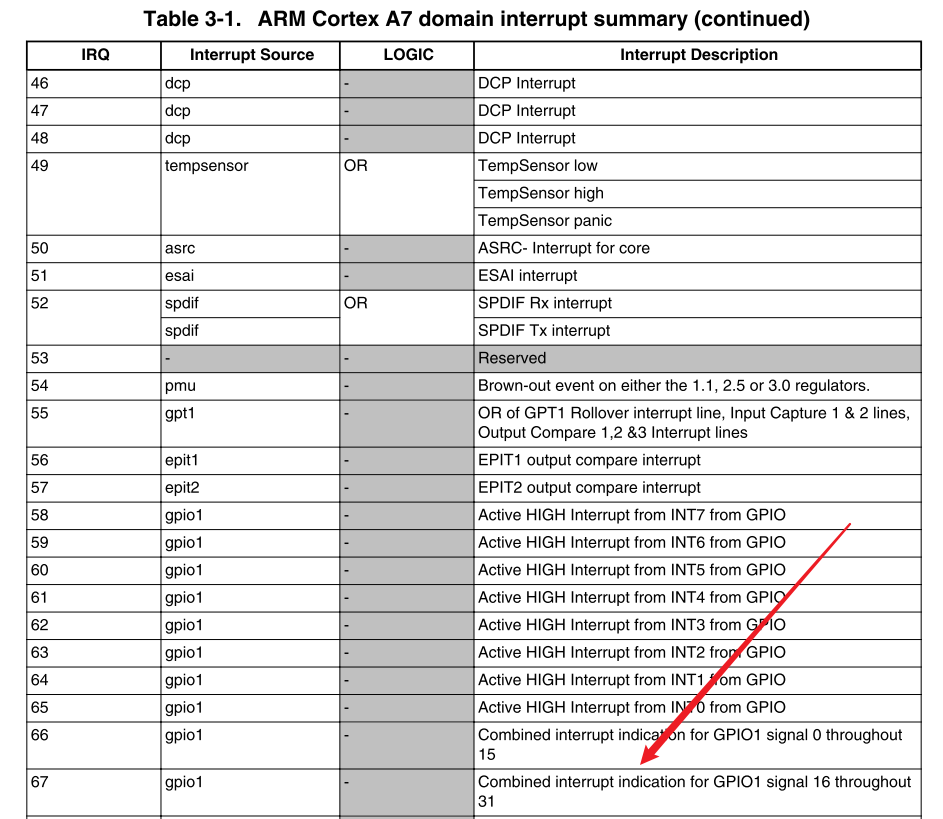
The specific configuration is as follows:
1. Enable 67 + 32 = 99 interrupt ID bits (the first 32 interrupt IDs are reserved for SPI and PPI interrupts)
2. Set interrupt priority
3. Register GPIO1_IO18 interrupt handling function
7. key related code implementation
Code design idea:
1. Set GPIO1_IO18 pin multiplexing function
2. Set GPIO1_IO18 pin level attribute
3. Set GPIO1_IO18 pin is the input
4. Configuration interrupt
- Open gpio1_ Corresponding channel of io18 pin
- Register interrupt service function
- Open interrupt
5. The function of interrupt service function is to turn the led light on and off.
1,key.h
#ifndef __KEY_H__
#define __KEY_H__

void key_init(void);
int key_get_value(void);
int key_get_status(void);
void gpio1_io18_irqhandler(void);
#endif
2,key.c
#include "key.h"
#include "imx6ull.h"
#include "delay.h"
#include "imx6ull_gpio.h"
#include "int.h"
#include "led.h"

void key_init(void)
{
    gpio_pin_config_t pin_config;
    pin_config.direction = GPIO_INPUT;
    pin_config.interruptMode = kGPIO_IntFallingEdge;

    /* 1,Initialize IO multiplexing to GPIO1_IO18 */
    IOMUXC_SetPinMux(IOMUXC_UART1_CTS_B_GPIO1_IO18, 0);

    /* 2,,Configure uart1_ CTS_ IO attribute of B
     * bit 16:0 HYS close
     * bit [15:14]: 11 Default 22K pull-up
     * bit [13]: 1 pull function
     * bit [12]: 1 pull/keeper Enable
     * bit [11]: 0 Turn off the open circuit output
     * bit [7:6]: 10 Speed 100Mhz
     * bit [5:3]: 000 Close output
     * bit [0]: 0 Low conversion rate
     */
    IOMUXC_SetPinConfig(IOMUXC_UART1_CTS_B_GPIO1_IO18, 0xF080);
    /* 3,Initialize GPIO GPIO1_IO18 set as input*/
    gpio_init(GPIO1,18,&pin_config);
    /* 4,Interrupt configuration */
    GIC_EnableIRQ(GPIO1_Combined_16_31_IRQn);				/* Enable the corresponding interrupt in GIC */
    imx6ull_register_irqhandler(GPIO1_Combined_16_31_IRQn, (imx6ull_irq_handler_t)gpio1_io18_irqhandler, NULL);	/* Register interrupt service function */
    gpio_enableint(GPIO1, 18);								/* Enable gpio1_ Interrupt function of io18 */
}

int key_get_value(void)
{
    return gpio_pinread(GPIO1,18);
}

int key_get_status(void)
{
    static unsigned char key_status = 1; // In the default state, the key is released and KEY0 is high

    if((key_status == 1)&&(key_get_value() == 0)){
        // Press the key
        delay(10);  // Debounce
        if(key_get_value() == 0){
            key_status = 0; // Press the key
            return 1;
        }
    }else{
        key_status = 1;
        return 2;
    }

    return 0;
}

/*
 * @description			: GPIO1_IO18 Final interrupt handling function
 * @param				: nothing
 * @return 				: nothing
 */
void gpio1_io18_irqhandler(void)
{
	static unsigned char state = 0;

	/*
	 *Delay jitter elimination is adopted. Delay function is prohibited in interrupt service function! Because of service interruption
	 *Go in and out!! For demonstration, the delay function is used to eliminate chattering, which will be explained later
	 *Timer interrupt elimination method!!!
 	 */

	delay(10);
	if(gpio_pinread(GPIO1, 18) == 0)	/* The button is pressed  */
	{
		state = !state;
		if(state == 0){
            led_off();
        }else if(state == 1){
            led_on();
        }
	}

	gpio_clearintflags(GPIO1, 18); /* Clear interrupt flag bit */
}
3,main.c
#include "imx6ull.h"
#include "clock.h"
#include "delay.h"
#include "led.h"
#include "key.h"
#include "int.h"

int main(void)
{
    int_init();
    clk_enable();
    led_init();
    key_init();
    while(1){

    }
    return 0;
}
4, Compile test
The compilation process is as follows:
onlylove@ubuntu:~/linux/driver/board_driver/6_int$ make
arm-linux-gnueabihf-gcc -Wall -nostdlib -c -O2  -I imx6ull/inc  -I bsp/clock  -I bsp/delay  -I bsp/led  -I bsp/key  -I bsp/int  -I user -o obj/start.o user/start.s
user/start.s: Assembler messages:
user/start.s: Warning: end of file not at end of a line; newline inserted
arm-linux-gnueabihf-gcc -Wall -nostdlib -c -O2  -I imx6ull/inc  -I bsp/clock  -I bsp/delay  -I bsp/led  -I bsp/key  -I bsp/int  -I user -o obj/imx6ull_gpio.o imx6ull/src/imx6ull_gpio.c
arm-linux-gnueabihf-gcc -Wall -nostdlib -c -O2  -I imx6ull/inc  -I bsp/clock  -I bsp/delay  -I bsp/led  -I bsp/key  -I bsp/int  -I user -o obj/clock.o bsp/clock/clock.c
arm-linux-gnueabihf-gcc -Wall -nostdlib -c -O2  -I imx6ull/inc  -I bsp/clock  -I bsp/delay  -I bsp/led  -I bsp/key  -I bsp/int  -I user -o obj/delay.o bsp/delay/delay.c
arm-linux-gnueabihf-gcc -Wall -nostdlib -c -O2  -I imx6ull/inc  -I bsp/clock  -I bsp/delay  -I bsp/led  -I bsp/key  -I bsp/int  -I user -o obj/led.o bsp/led/led.c
arm-linux-gnueabihf-gcc -Wall -nostdlib -c -O2  -I imx6ull/inc  -I bsp/clock  -I bsp/delay  -I bsp/led  -I bsp/key  -I bsp/int  -I user -o obj/key.o bsp/key/key.c
arm-linux-gnueabihf-gcc -Wall -nostdlib -c -O2  -I imx6ull/inc  -I bsp/clock  -I bsp/delay  -I bsp/led  -I bsp/key  -I bsp/int  -I user -o obj/int.o bsp/int/int.c
arm-linux-gnueabihf-gcc -Wall -nostdlib -c -O2  -I imx6ull/inc  -I bsp/clock  -I bsp/delay  -I bsp/led  -I bsp/key  -I bsp/int  -I user -o obj/main.o user/main.c
arm-linux-gnueabihf-ld -Timx6ul.lds -o int.elf obj/start.o obj/imx6ull_gpio.o obj/clock.o obj/delay.o obj/led.o obj/key.o obj/int.o obj/main.o
arm-linux-gnueabihf-objcopy -O binary -S int.elf int.bin
arm-linux-gnueabihf-objdump -D -m arm int.elf > int.dis
onlylove@ubuntu:~/linux/driver/board_driver/6_int$
Test on the development board, and the keys work normally.