The previous articles, from the most basic register lighting, to the device tree lighting, and then to the lighting of GPIO subsystem, have a step-by-step understanding of various lighting principles of embedded Linux development.
Lighting uses the output function of GPIO. In this article, learn the use of GPIO input function through the use of keys.
1 Hardware introduction
1.1 schematic diagram of keys on the board
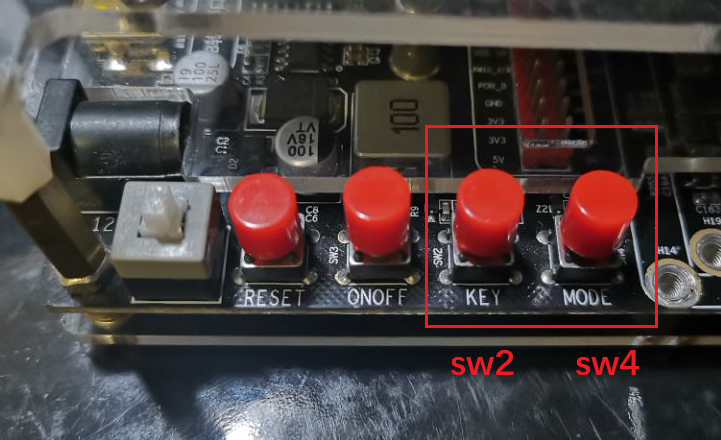
Let's look at the schematic diagram first. There are four buttons sw1~sw4 on my board:
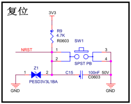
1.1.1 SW1
SW1 is the system reset key of the board, which is not programmable
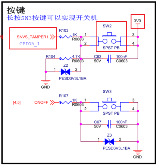
1.1.2 SW2,SW3
-
SW2: SNVS_TAMPER1,GPIO5_1
Normally, it is low level, and pressing it is high level.
-
SW3: ONOFF
It is also a system level key, which is used to turn on and off the machine by long pressing.
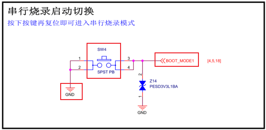
1.1.3 SW4
SW4 is BOOT_MODE1 pin is used to switch the serial burning mode, which needs to be used with the reset key.
This article only tests the function of the key, so you can use the key.
1.1.4 use two of the keys
The functional characteristics of the four keys on the board are as follows:
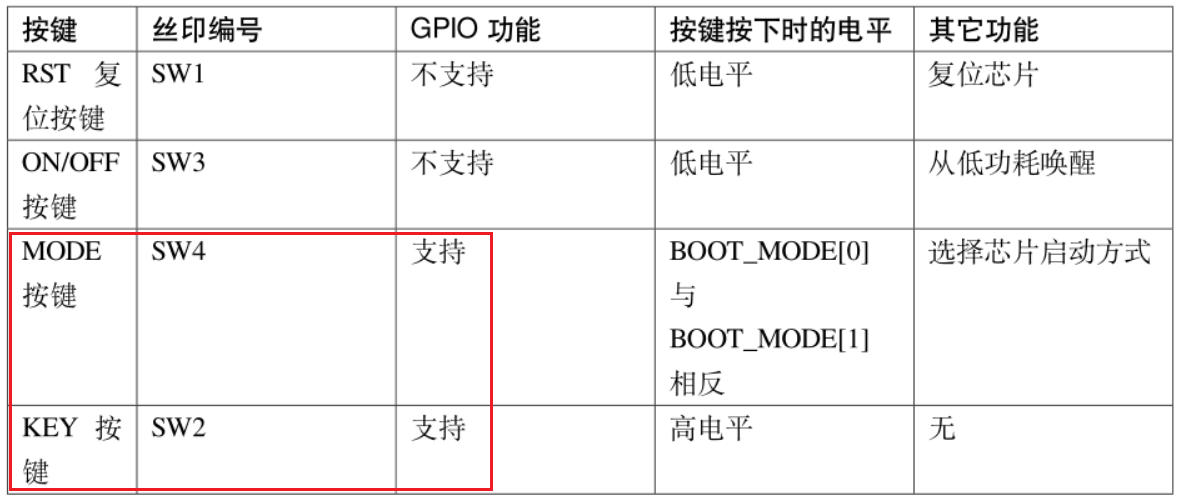
In this experiment, two keys SW2 and SW4 are used for the experiment.
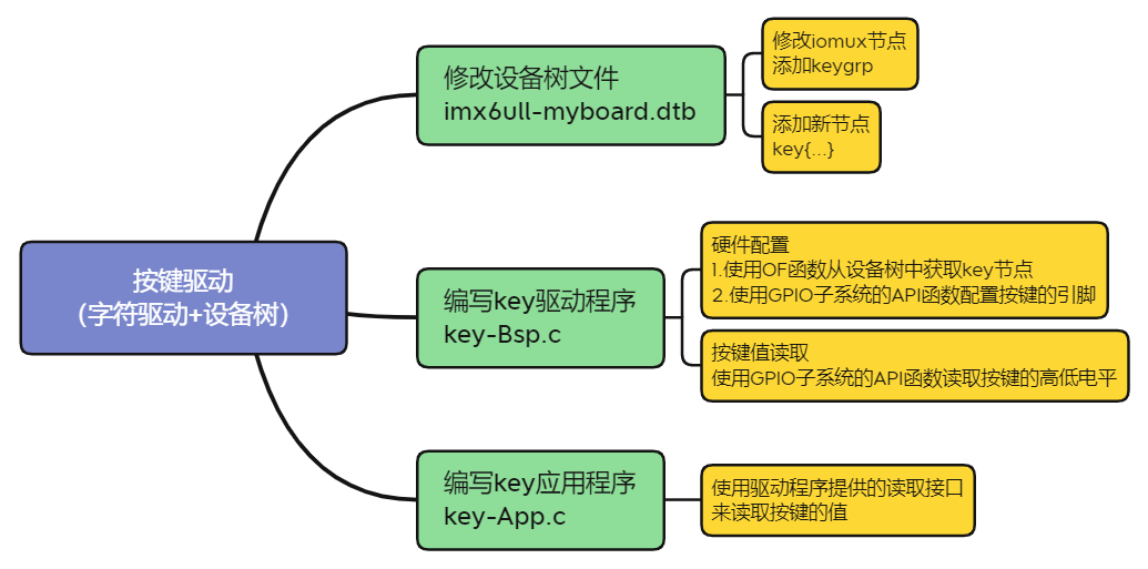
2 software preparation
2.1 modify equipment tree file
2.1.1 modifying iomuxc nodes
Modify imx6ull-myboard.dts and create a pinctrl under the imx6ull evk byte point of the iomuxc node_ The child node of key. The node contents are as follows:
pinctrl_key: keygrp {
    fsl,pins = <
        MX6ULL_PAD_SNVS_TAMPER1__GPIO5_IO01    0x3080 /* SW2 */
        MX6ULL_PAD_BOOT_MODE1__GPIO5_IO11      0xF080 /* SW4 */
    >;
};
This part is to configure the pins. The definitions of these two pins are in the imx6ull pinfunc snvs. H file:
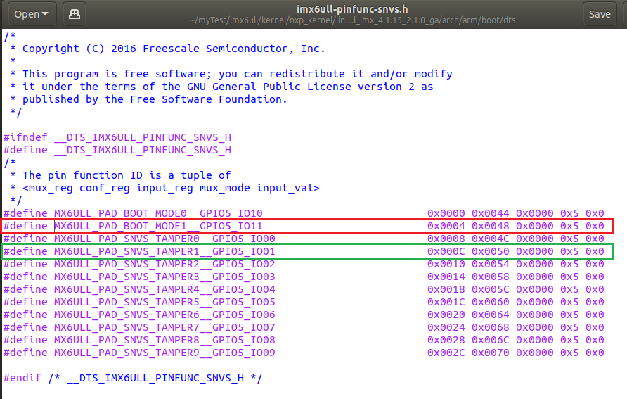
The value after the pin macro definition is the configuration of the pin function:
SW2: 0x3080, i.e. 0011 0000 1000 0000
SW4: 0xF080, i.e. 1000 0000
Compare with the previous explanation of GPIO PAD register configuration , pull up or pull down according to the actual circuit configuration of the two keys.
/*
*bit 16:0 HYS close
*bit [15:14]: [00]Pull down [01]47k pull up [10]100k pull up [11]22k pull up<---
*bit [13]: [0]kepper Function [1]pull function
*bit [12]: [0]pull/keeper-disable [1]pull/keeper-enable
*bit [11]: 0 Turn off the open circuit output
*bit [10:8]: 00 Reserved value
*bit [7:6]: 10 Speed 100Mhz
*bit [5:3]: 000 Output Disable<---
*bit [2:1]: 00 Reserved value
*bit [0]: 0 Low conversion rate
*/
Note: the GPIO of SW4 (mx6ull_pad_boot_mode1_gpio5_io11) has actually been used by other devices (spi4).
At more than 300 lines of imx6ull-myboard.dts, there are:
pinctrl_spi4: spi4grp {
    fsl,pins = <
        MX6ULL_PAD_BOOT_MODE0__GPIO5_IO10        0x70a1
        MX6ULL_PAD_BOOT_MODE1__GPIO5_IO11        0x70a1
        MX6ULL_PAD_SNVS_TAMPER7__GPIO5_IO07      0x70a1
        MX6ULL_PAD_SNVS_TAMPER8__GPIO5_IO08      0x80000000
        >;
};
Theoretically, we should comment out the configuration here, because one IO cannot perform two functions at the same time. Since spi4 is not used in this experiment, let's ignore it for the time being to see what impact it will have. If it affects this experiment, note out the configuration here.
2.1.2 adding a key node
Create a key node named key under the root node, as follows:
key {
    #address-cells = <1>;
    #size-cells = <1>;
    compatible = "myboard-key";
    pinctrl-names = "default";
    pinctrl-0 = <&pinctrl_key>;
    key1-gpio = <&gpio5 1 GPIO_ACTIVE_HIGH>;   /* SW2 */
    key2-gpio = <&gpio5 11 GPIO_ACTIVE_LOW>;   /* SW4 */
    status = "okay";
};
2.2 writing key driver
The key driver also belongs to the character device driver. Like the previous character device driver framework, the main modification point is that the hardware initialization configuration of the key has been read.
Create a new key BSP. C
2.2.1 hardware initialization of keys
The initialization process is to use the OF function to obtain the key node from the device tree, and then use the API function OF the GPIO subsystem to configure GPIO as input.
static int keyio_init(void)
{
    keydev.nd = of_find_node_by_path("/key");
    if (keydev.nd== NULL)
    {
        return -EINVAL;
    }

    keydev.key1_gpio = of_get_named_gpio(keydev.nd ,"key1-gpio", 0);
    keydev.key2_gpio = of_get_named_gpio(keydev.nd ,"key2-gpio", 0);
    if ((keydev.key1_gpio < 0)||(keydev.key2_gpio < 0))
    {
        printk("can't get key\r\n");
        return -EINVAL;
    }
    printk("key1_gpio=%d, key2_gpio=%d\r\n", keydev.key1_gpio, keydev.key2_gpio);

    /* IO used to initialize key */
    gpio_request(keydev.key1_gpio, "key1");    /* Request IO */
    gpio_request(keydev.key2_gpio, "key2");    /* Request IO */
    gpio_direction_input(keydev.key1_gpio);    /* Set as input */
    gpio_direction_input(keydev.key2_gpio);    /* Set as input */
    return 0;
}
2.2.2 read the value of the key
Reading the value of the key is also an API function of the GPIO subsystem. After reading the value of the key, pass the value to the application layer for use. Note that atomic operation is used here_ Set and atomic_read implements data writing and reading.
/* Define key values */
#Define key1value 0x01 / * key value*/
#Define key2value 0x02 / * key value*/
#Define invalid 0x00 / * invalid key value*/

static ssize_t key_read(struct file *filp, char __user *buf, size_t cnt, loff_t *offt)
{
    int ret = 0;
    int value;
    struct key_dev *dev = filp->private_data;

    if (gpio_get_value(dev->key1_gpio) == 1)         /* key1 Press */
    {
        printk("get key1: high\r\n");
        while(gpio_get_value(dev->key1_gpio));       /* Wait for the key to release */
        atomic_set(&dev->keyvalue, KEY1VALUE);
    }
    else if (gpio_get_value(dev->key2_gpio) == 0)    /* key2 Press */
    {
        printk("get key2: low\r\n");
        while(!gpio_get_value(dev->key2_gpio));      /* Wait for the key to release */
        atomic_set(&dev->keyvalue, KEY2VALUE);
    }
    else
    {
        atomic_set(&dev->keyvalue, INVAKEY);        /* Invalid key value */
    }

    value = atomic_read(&dev->keyvalue);
    ret = copy_to_user(buf, &value, sizeof(value));
    return ret;
}
2.3 writing key application
Create a new key app. C
The application layer program of the key mainly reads the value of the key through the key reading interface provided by the driver, and prints the value of the key when the key is pressed.
/* Define key values */
#define KEY1VALUE   0X01
#define KEY2VALUE   0X02
#define INVAKEY     0X00

int main(int argc, char *argv[])
{
    int fd, ret;
    char *filename;
    int keyvalue;

    if(argc != 2)
    {
        printf("Error Usage!\r\n");
        return -1;
    }

    filename = argv[1];

    /* Open key driver */
    fd = open(filename, O_RDWR);
    if(fd < 0)
    {
        printf("file %s open failed!\r\n", argv[1]);
        return -1;
    }

    /* Cycle to read key value data! */
    while(1)
    {
        read(fd, &keyvalue, sizeof(keyvalue));
        if (keyvalue == KEY1VALUE)
        {
            printf("KEY1 Press, value = %#X\r\n", keyvalue);
        }
        else if (keyvalue == KEY2VALUE)
        {
            printf("KEY2 Press, value = %#X\r\n", keyvalue);
        }
    }

    ret= close(fd); /* Close file */
    if(ret < 0)
    {
        printf("file %s close failed!\r\n", argv[1]);
        return -1;
    }
    return 0;
}
3 experimental test
3.1 compiler
3.1.1 compiling device tree
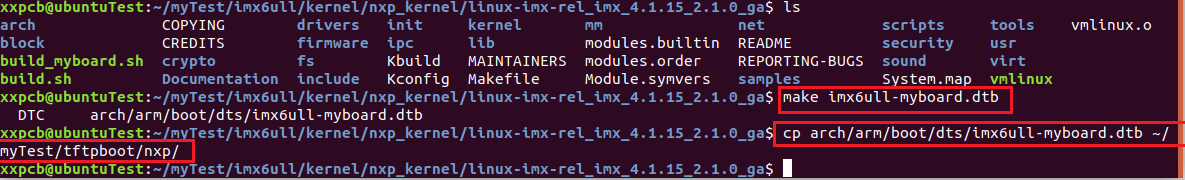
Compile the device tree file and copy the compiled dtb file to the startup folder:
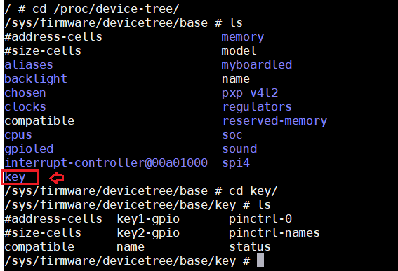
Start the development board in network mode and view the key node:
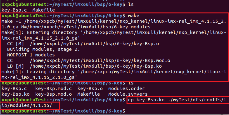
3.1.2 compiling key driver
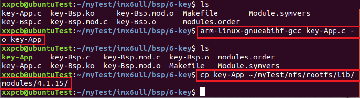
3.1.3 compiling key application
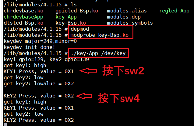
3.2 testing
3.3 viewing CPU utilization
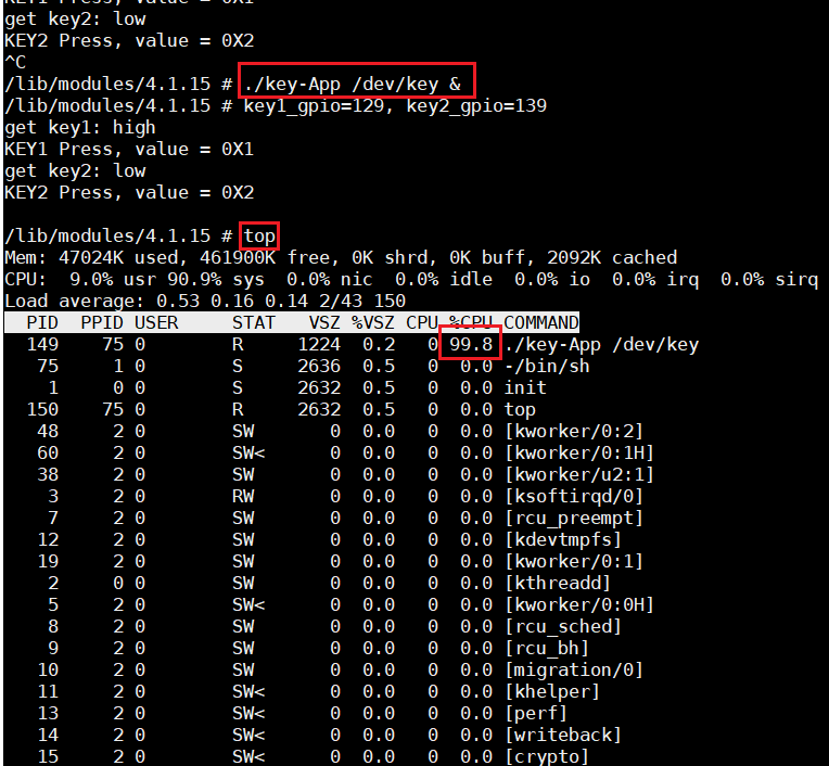
First, Ctrl+C ends the key pressing process, and then use the following command to run the key pressing program in the background:
./key-App /dev/key &
Then use the command:
top
To view CPU usage. As can be seen from the figure below, the CPU utilization rate is 99.8%, which is occupied by the key check program, because there is a while loop in the key program that always reads the value of the key.
Use instructions:
ps
Check the process number of the key, as shown in the following figure: 149, and then use it:
kill -9 149
To kill the key process, and then use the top command to view it. You can see that the CPU utilization has changed back to 0.
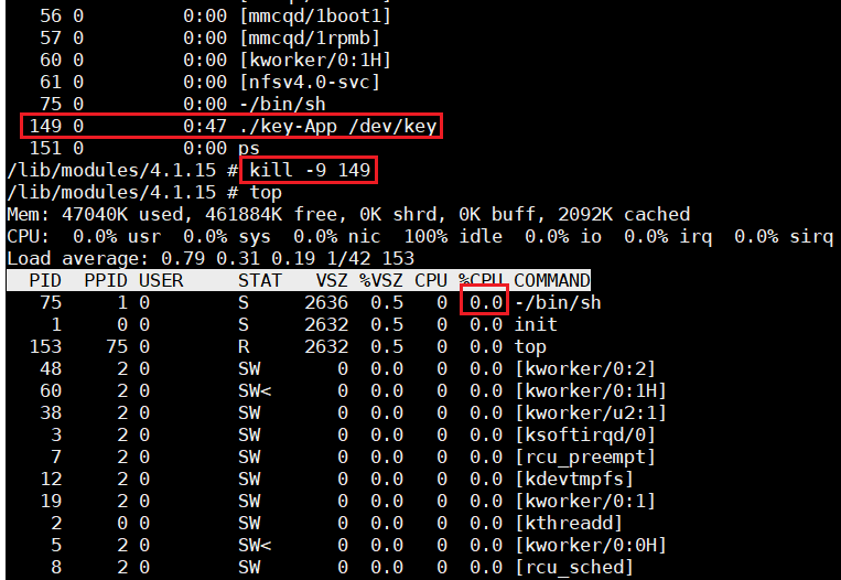
In the actual use of keys, this method of continuous detection leading to full CPU is generally not used. This article only introduces the use of GPIO input function first, and then uses a more efficient key detection mechanism to realize the key detection function.
4 Summary
This paper mainly introduces the use of key detection of i.MX6ULL. The main knowledge points are the modification of device tree, input configuration of GPIO and reading of high and low levels.
9273864)]
Use instructions:
ps
Check the process number of the key, as shown in the following figure: 149, and then use it:
kill -9 149
To kill the key process, and then use the top command to view it. You can see that the CPU utilization has changed back to 0.
[external chain picture transferring... (img-PzEE8jzz-1636469273866)]
In the actual use of keys, this method of continuous detection leading to full CPU is generally not used. This article only introduces the use of GPIO input function first, and then uses a more efficient key detection mechanism to realize the key detection function.
4 Summary
This paper mainly introduces the use of key detection of i.MX6ULL. The main knowledge points are the modification of device tree, input configuration of GPIO and reading of high and low levels.