preface
Digital filtering technology is an important part of digital signal processing, and the design of filter is one of the core problems of signal processing. IIR(Infinite Impulse Response) digital filter, also known as "infinite impulse response digital filter" or "recursive filter", is generally considered to have infinite impulse response.
Learning objectives:
- Understand and be familiar with IIR filter structure;
- Understand the basic knowledge and prototype design of analog filter;
- Master frequency band conversion;
- The impulse response invariable method and bilinear transformation method are realized;
- Understand the minimum order selection of filter;
- Understand and implement filter design.
1. IIR filter structure
Digital filter is a discrete-time linear time invariant system realized by finite precision algorithm to complete the function of signal filtering (the process of eliminating or weakening noise and extracting useful signal according to the different characteristics of useful signal and noise).
Similar to analog filter, digital filter is also a frequency selection device. It attenuates the frequency component of useful signal very little to make it pass smoothly, and attenuates the frequency component of noise and other interference signals to a large extent to prevent them from passing as far as possible. Compared with analog filter, digital filter has high stability, high precision and strong flexibility. A digital filter can be expressed as a system function
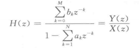
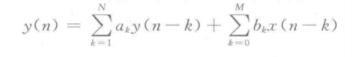
From this system function, the constant coefficient linear difference equation representing the relationship between input and output of the system can be obtained as
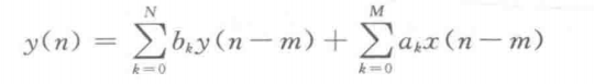
It can be seen that the function of digital filter is to transform the input sequence x(n) into MATLAB signal processing output sequence y(n) through certain operation. Different operation and processing methods determine the different implementation structures of the filter.
The unit sampling response h(n) of infinite impulse response filter is infinite. For a given system function of linear time invariant system, there are various equivalent difference equations or network structures. Because multiplication is a time-consuming operation, each delay unit must have a storage register.
Therefore, the network structure with the least Changshu multiplier and the least delay branch is the common choice in order to improve the operation speed and reduce the memory. However, when the effect of limited register length needs to be considered, the structure of least multiplier and delay unit is often not used.
The basic structures of IIR filter include direct type, cascade type and parallel type, which are introduced below.
1.1 direct type
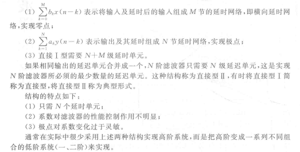
The N-order difference equation of direct type I system input-output relationship is
The advantages are as follows:
In MATLAB, the filter function is provided to realize the direct form of IIR. The calling format is as follows:
y= filter(b,a,X)
In the command, b represents the coefficient matrix of the numerator polynomial of the system transfer function, a represents the coefficient matrix of the denominator polynomial of the system transfer function, x represents the input sequence, and y represents the output sequence.
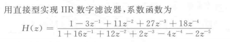
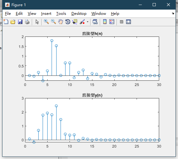
Find the output of unit impulse response and unit step response
Implementation code:
clc;
close all;
b = [1,-3,11,27,18];
a = [16,12,2,-4,-2];
N = 30;
delta = impz(b,a,N);%Impulse response
x = [ones(1,5),zeros(1,N-5)];	%Step response

h = filter(b,a,delta);
y = filter(b,a,x);

subplot(211);stem(h);title('Direct type h(n)');
subplot(212);stem(y);title('Direct type y(n)');
In MATLAB, the filter function is provided to realize the direct form of IIR. The calling format is as follows: y= filter(b,a,X)
In the command, b represents the coefficient matrix of the numerator polynomial of the system transfer function, a represents the coefficient matrix of the denominator polynomial of the system transfer function, x represents the input sequence, and y represents the output sequence.
1.2 cascade type
The system function is decomposed according to zero and pole
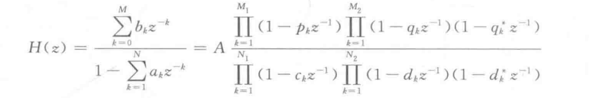
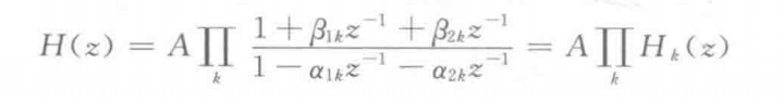
Combine the conjugate factors, there are
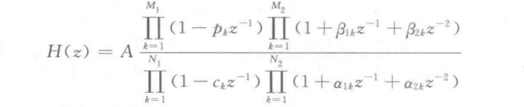
The second-order factor form of complete decomposition of H(z) into real coefficients is
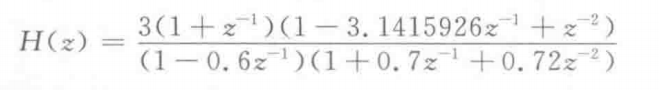
For example, the following system functions are implemented with cascade structure
function[x,n] = impseq(n0,ns,nf)
% ns=The starting point of the sequence; nf=The end point of the sequence; n0=Sequence in n0 There is a unit pulse at.
% x=The unit sampling sequence generated; n=Generate sequence location information
n = [ns:nf];
x = [(n-n0)==0];
end
function y= casfilter(b0,B,A,x)
    [K L]= size(B);
    N = length(x);
    w = zeros(K+1,N);
    w(1,:) = x;
    for i=1:1:K
        w(i+ 1,:) = filter(B(i,:),A(i,:),w(i,:));
    end
    y = b0* w(K+1,:);
%IIR Cascade implementation of filter
%y= casfilter(b0,B,A,x)
%y For output
%b0=Gain coefficient
%B Including each factor coefficient bk of K Row 3 column matrix
%A=Including each factor coefficient ak of K Row 3 column matrix
%x For input
end
clear
b0 = 3;
N = 30;
B=[1,1,0;1, -3.1415926,1];
A=[1,-0.6,0;1,0.7,0.72];
delta = impseq(0,0,N);
x= [ones(1,5),zeros(1,N-5)];
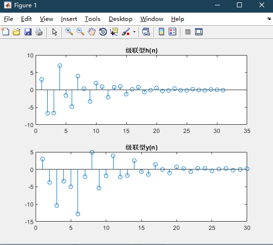
h = casfilter(b0,B,A,delta); %Cascaded unit impulse response
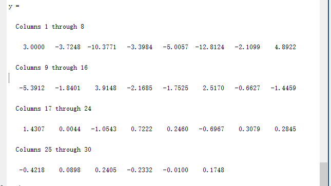
y = casfilter(b0,B, A,x) %Cascade output response
subplot(211);
stem(h);title('Cascade type h(n)');
subplot(212);
stem(y);title('Cascade type y(n)');
1.3 parallel type
The factorized H(z) is expanded into the form of partial fraction, and the basic structure of parallel IIR is obtained as follows
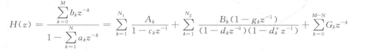
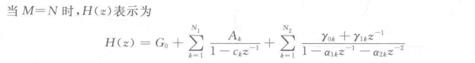
The conjugate pole is transformed into a second-order polynomial with real coefficients
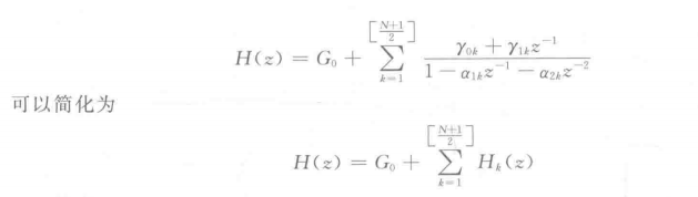
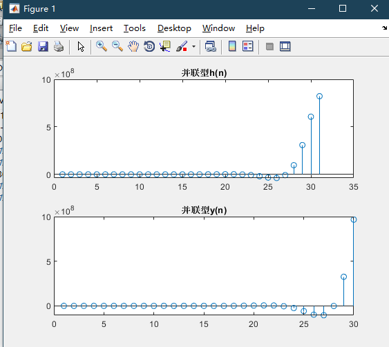
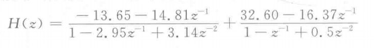
IIR digital filter is realized by parallel structure, and the system function is
Find the output of unit impulse response and unit step response.
The realization procedure of parallel structure is as follows:
function y= parfiltr(C,B,A,x)
%IIR Parallel implementation of filter
%y= parfiltr(C,B,A,x)
%y For output
%C For when B The length of is equal to A The length of the polynomial
%B=Including each factor coefficient bk of K Row two-dimensional real coefficient matrix
%A=Including each factor coefficient ak of K Row 3D real coefficient matrix
%x For input
    [K,L] = size(B);
    N= length(x);
    w= zeros(K+ 1,N);
    w(1,:) = filter(C,1,x);
    for i= 1:1:K
        w(i+ 1,:)= filter(B(i,:),A(i,:),x);
    end
    y= sum(w);
end
The MATLAB program code is as follows:
clear
C=0;
N= 30;
B=[-13.65, -14.81;32.60,16.37];
A=[1,-2.95,3.14;1,-1,0.5];
delta= impseq(0, 0, N);
x= [ones(1,5), zeros(1,N-5)];
h= parfiltr(C, B, A, delta);
%Parallel unit impulse response,delta It refers to increment and difference
y= parfiltr(C,B,A,x);
%Parallel output response
subplot(211);stem(h);
title('Parallel type h(n)');
subplot(212);stem(y);
title('Parallel type y(n)');