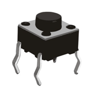
1 Introduction to independent keys
The keyboard is divided into coded keyboard and non coded keyboard. The recognition of the closing key on the keyboard is realized by a special hardware encoder, and the key coding number or key value is called the coding keyboard, such as the computer keyboard. The keyboard identified by software programming is called non coding keyboard. In various systems composed of single chip microcomputer, non coding keyboard is more used. Non coding keyboard is divided into independent keyboard and determinant keyboard (often referred to as matrix keyboard).
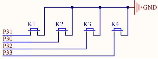
The IO port of the single chip microcomputer can be used as both output and input. When detecting the key, its input function is used. We ground one end of the key and connect the other end with an I/O port of the single chip microcomputer. At the beginning, assign a high level to the IO port, and then let the single chip microcomputer constantly detect that the I/O port changes from apricot to low level. When the key is closed, That is, the I/O port is connected to the ground through the key and becomes a low level. Once the program detects that the I/O port becomes a low level, it indicates that the key is pressed, and then execute the corresponding command.
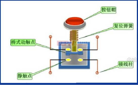
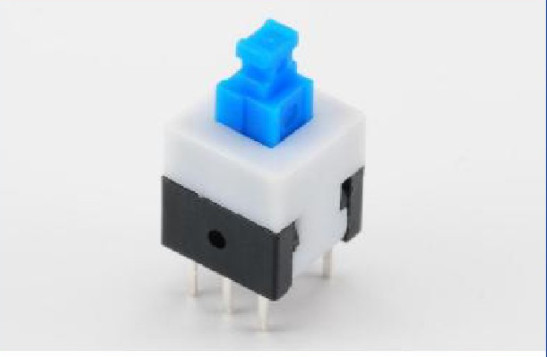
Note: self locking switch: it is a common button switch. When the switch button is on time for the first time, the switch is on and maintained, that is, self-locking. When the switch button is on time for the second time, the switch is off and the button pops up.
2 principle of mechanical key
Due to the elastic action of mechanical contacts, a key switch will not be stably connected immediately when it is closed, and will not be completely disconnected at once when it is disconnected. Instead, it is accompanied by a series of jitters at the moment of closing and opening. Because the speed of detecting IO port by single chip microcomputer is very fast, which exceeds the frequency of shrapnel jitter, the influence of key jitter should be eliminated when detecting the key state. It is generally believed that the jitter shall not exceed 10ms.
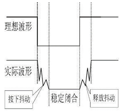
In order to avoid this phenomenon, the measure to do is to press the key to eliminate chattering. The methods of eliminating chattering are divided into hardware and software.
(1) Hardware dithering
A capacitor (RC circuit) is connected in parallel on the key, and the voltage burr generated in the jitter process is smoothed by using the charge and discharge characteristics of the capacitor, so as to eliminate the jitter.
(2) Software dithering
When the key state change is detected, wait for a delay time of about 10ms, and then detect the key state again after the jitter disappears. If the state is the same as that just detected, you can confirm that the key has been stably operated.
a) After checking that the key is pressed, conduct a 10-15ms delay to skip this jitter area;
b) Monitor the key status after delay. If it is not pressed, it indicates that it is caused by jitter or interference. If it is still pressed, it can be considered as a real press. And carry out corresponding operations.
3) Similarly, after the key is released, the jitter removal delay shall also be carried out. After the delay, monitor whether the key is really released.
3. Functional requirements: control LED1-LED4 indicator lights on and off respectively through independent keys K1-K4 on the development board.
4 hardware design
5 software design
 1 #include "reg52.h"
 2
 3 typedef unsigned char u8;
 4 typedef unsigned int  u16;
 5
 6 //Define independent key control pins and input signals
 7 sbit KEY1 = P3^1;
 8 sbit KEY2 = P3^0;
 9 sbit KEY3 = P3^2;
10 sbit KEY4 = P3^3;
11
12 //definition LED Control pin, output signal
13 sbit LED1 = P2^0;
14 sbit LED2 = P2^1;
15 sbit LED3 = P2^2;
16 sbit LED4 = P2^3;
17
18 //Use the macro to define the key value pressed by the independent key and which key is different
19 #define KEY1_PRESS         1
20 #define KEY2_PRESS         2
21 #define KEY3_PRESS         3
22 #define KEY4_PRESS         4
23 #define KEY_UNPRESS     0
24
25 //Delay function, when ten_us=1 When, the delay is about 10 minutes us
26 void delay_10us(u16 ten_us)
27 {
28      while(ten_us--);
29 }
30
31 //The key monitoring function is used to monitor which of the four keys is pressed, and it will return a value
32 u8 key_scan(u8 mode)
33 {
34      static u8     key = 1;   //Static variable, which can keep the last value
35
36     if(mode)    key = 1;   //mode=1,Continuous scan key(Long press);mode=1, Single scan key (short press)
37
38     if(key==1&&(KEY1==0||KEY2==0||KEY3==0||KEY4==0)) //Press any key
39     {
40         delay_10us(1000);    //Delay 10 ns,Filter out the pressing jitter process
41         key = 0;
42         if(KEY1 == 0)
43             return KEY1_PRESS;    //After de chattering, it is monitored again KEY1 Press to return to the code value of key 1
44         else if(KEY2 == 0)
45             return KEY2_PRESS;
46         else if(KEY3 == 0)
47             return KEY3_PRESS;
48         else if(KEY4 == 0)
49             return KEY4_PRESS;
50     }
51     else if(KEY1==1 && KEY2==1 && KEY3==1 && KEY4==1) //No key is pressed, and they are all at high level at the same time
52     {
53          key = 1;      //For the next operation of the key
54     }
55     return KEY_UNPRESS;
56 }
57
58 void main()
59 {
60     u8 key_value = 0;
61
62     while(1)
63     {
64          key_value = key_scan(0);
65
66         if(key_value == KEY1_PRESS)        //Monitored KEY1 Press, control LED1 State flip
67             LED1 = !LED1;
68         else if(key_value == KEY2_PRESS)
69             LED2 = !LED2;
70         else if(key_value == KEY3_PRESS)
71             LED3 = !LED3;
72         else if(key_value == KEY4_PRESS)
73             LED4 = !LED4;
74     }
75 }
6 experimental phenomena
After the development board is successfully connected to the computer with USB cable (the computer can recognize the CH340 serial port on the development board), the compiled HEX files are burned into the chip. The phenomena are as follows: when K1 key is pressed, LED1 indicator light is on; Press K1 key again, LED1 indicator light goes out, and cycle like this.
7 others
Four elements of independent keys:
"Self locking": once the key enters the low level, it should "self lock" to avoid constantly triggering the key. Only when the key is released to the high level can it be "unlocked" in time to prepare for the next trigger.
"Shake elimination": the key is a mechanical contact device. There must be micro mechanical shake at the moment of contact. The moment when it is fed back to the level is "high, low, high, low..." this unstable level state is a kind of interference. However, once the key is pressed and stabilized, this state disappears and the level remains stable at a low level. The essence of chattering elimination is filtering. It is necessary to filter out the instantaneous jitter of contact and avoid "one press and multiple triggers" of keys.
"Non blocking": delay must be used when dealing with jitter elimination. If blocked delay is used at this time, it will affect the operation efficiency of other tasks. Therefore, non blocking timing delay has more advantages.
"Zero clearing filtering": there are two states in the process of eliminating chattering. The first state is to judge the state of two levels, and a "fixed time" delay is inserted in the middle. This method has been judged twice before and after. The first time is to enter the delayed state when the low level is recognized, and the second time is to confirm whether it continues to be the low level state after the delay. The disadvantage of this method is, The "fixed time" depends on the empirical value, but the jitter time length of different keys is different. In addition, it is only judged twice before and after. It is also much weaker in the anti-interference ability of the software, and the "password level" is not high enough. The second realm is "zero clearing filter". The "zero clearing filter" is very ingenious and has strong anti-interference ability. It can automatically filter the "jitter time" of different keys, and then enter the "N-times identification judgment" of a "stable time". What is more ingenious is that once it is found that there is a high-level interference in both "jitter time" and "stable time", Automatically reset the timer immediately and restart the timing. "Stabilization time" is generally taken between 20ms and 30ms, while "jitter time" is hidden. It is not directly described in the code, but it is invisibly integrated into the code. Its existence can be found only by slowly experiencing it.
8 references
(1)(78 messages) use of independent keys_ feiffer · hu's blog - CSDN blog_ Independent key;
(2)(79 messages) c51 independent key_ Cao's blog - CSDN blog_ c51 independent key program;