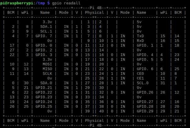
First, learn about the GPIO distribution of raspberry pie. You can get the GPIO distribution by entering gpio readall.
The error of Oops - unable to determine board type... model: 17 may be due to the version of wiringPi,
Enter the following command to upgrade the wiringPi version
cd /tmp
wget https://project-downloads.drogon.net/wiringpi-latest.deb
sudo dpkg -i wiringpi-latest.deb
Once you know the IO distribution, you can start programming io.
Import library:
import RPi.GPIO as GPIO
Input and output
1. Set pin mode:
GPIO.setmode(GPIO.BMC/BOARD) #BMC or BOARD mode
Note that the io number of BMC is different from that of BOARD. See io distribution for details
2. Set pin as input:
GPIO.setup(pin,GPIO.IN)

GPIO.setup(pinx,GPIO.IN,pull_up_down=GPIO.PUD_UP/GPIO.DOWN)#You can adjust the up-down status
3. Set initialization output high and low levels:
GPIO.setup(pin,GPIO.OUT,initial=GPIO.HIGH/GPIO.LOW)
Of course, the advantage of python is that it can create a list, and then bring the list into the function to execute the input and output of multiple pins at one time, such as:
PinList=[pin1,pin2,pin3]

GPIO.setup(PinList,GPIO.IN)
By creating a list and adding the definition of pins to the list, multiple pins can be set as inputs at the same time.
4. Read io status
GPIO.input(pinx) #The input() method can read the high and low levels of the pinx pin
interrupt
wait_for_edge():
Used to execute a function when an edge is detected
import RPi.GPIO as GPIO  ##Introduction of GPIO module
import time              ##Import time library
touchPin = 18

GPIO.setmode(GPIO.BCM)
GPIO.setup(touchPin, GPIO.IN)
print 'Ready to start receiving'

GPIO.wait_for_edge(touchPin, GPIO.RISING)
print 'Low voltage change found high voltage'

GPIO.wait_for_edge(touchPin, GPIO.FALLING)
print 'High voltage change low voltage found
event_detect() series functions:
Monitor a pin. Once the pin input changes, call event_ The detected() function returns True.
| function | Parameter meaning | Function meaning |
| add_event_detect( channel, status, bouncetime=300) | Sensor pin, status to be detected | Register an event to detect whether status is found |
| event_detected( channel) | Pin to be detected | Check whether the status status is detected by the detection pin |
| add_event_callback( channel, callback) | Sensor pin, callback function | Find the specified status, and then call back to execute the custom method |
| remove_event_detect( channel) | Pin to be detected | Stop edge detection |
Note: the optional values of status are GPIO.RISING, GPIO.FALLING and GPIO.BOTH; Bounce time is the jitter time, which is used for software anti jitter, in milliseconds.
Serial port:
It needs to be modified before use / boot/cmdline.txt and / boot/config.txt
Enter the following command
sudo nano /boot/cmdline.txt
#Change the content to
dwc_otg.lpm_enable=0 console=tty1 root=/dev/mmcblk0p2  rootfstype=ext4 elevator=deadline fsck.repair=yes  rootwait

sudo nano /boot/config.txt
#Add at the end
dtoverlay=pi3-miniuart-bt
enable_uart=1
Installing the python serial module
sudo apt-get install python-serial
Restart raspberry pie after these configurations
The following is the test serial port code, (echo function)
# -*- coding: utf-8 -*
import serial
import time
# Open serial port
ser = serial.Serial("/dev/ttyAMA0", 9600)
def main():
    while True:
        # Get receive buffer characters
        count = ser.inWaiting()
        if count != 0:
            # Read and echo
            recv = ser.read(count)
            ser.write(recv)
        # Clear receive buffer
        ser.flushInput()
        # Necessary software delay
        time.sleep(0.1)

if __name__ == '__main__':
#If this file is run as a script
    try:
        main()
    except KeyboardInterrupt:
    #exception handling
        if ser != None:
            ser.close()
PWM:
Pwm=GPIO.PWM(pin,frequence) #Create PWM instance

Pwm.start(dc) #Start PWM dc value (duty cycle)

Pwm.ChangeFrequency(freq) #Change PWM frequency

Pwm.ChangeDutyCycle(dc) # Change the duty cycle of PWM 0.0 < = DC < = 100

Pwm.stop() #Stop PWM
Example of LED light and dark pwm
import time
import RPi.GPIO as GPIO
GPIO.setmode(GPIO.BOARD)
GPIO.setup(12, GPIO.OUT)

p = GPIO.PWM(12, 50)  # The channel is 12 and the frequency is 50Hz
p.start(0)
try:
    while 1:
        for dc in range(0, 101, 5):
            p.ChangeDutyCycle(dc)
            time.sleep(0.1)
        for dc in range(100, -1, -5):
            p.ChangeDutyCycle(dc)
            time.sleep(0.1)
except KeyboardInterrupt:
    pass
p.stop()
GPIO.cleanup()