1. Preface
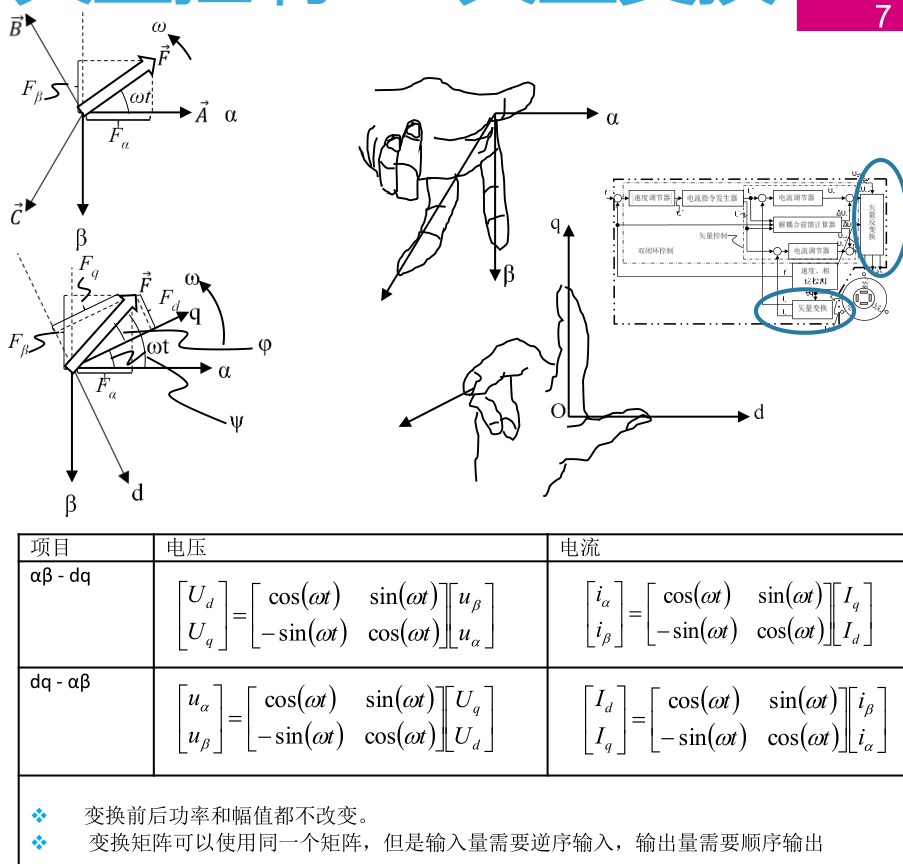
The following figure shows the coordinate system defined in the PPT of ST training materials. It can be seen that there are two main differences from the common coordinate system definitions:
- The beta axis defined by ST is downward, while the common beta axis is upward. This definition is related to the European custom of defining the y-axis downward. This will only affect the Clarke transformation, making the result of beta axis a minus sign from the common result;
- The electrical angle theta defined by ST is the angle between q-axis and alpha axis, while the common definition is the angle between d-axis and alpha axis. This will cause the result of Park transformation to be completely opposite to the common result (exchange dq axis). In fact, the physical effect is the same.
2.Clarke transform
- Solved: the function of Clarke transformation is easy to understand, and the problem is not very big. Since the electric angle theta is not involved, the result is only a minus sign between the beta axis result and the common result. And notice the front in the Clarke transform of ST × The coefficient is 2 / 3.
- Legacy: for the problem in line 41 of the program, why should we limit the amplitude at the minimum value? In fact, there is no overflow at this time, and the change value is very small.
// Clarke transformation is not a big problem. Two main points should be noted:
// 1. Front in Clark transform × The coefficient is 2 / 3
// 2. The established coordinate system alpha is the same as the common one, but the beta coordinate system is downward, so it is a minus sign from the general result
alphabeta_t mc_clark(ab_t input)
{
	alphabeta_t output;

	int32_t a_divSQRT3_tmp, b_divSQRT3_tmp ;
	int32_t wbeta_tmp;
	int16_t hbeta_tmp;

	/* qIalpha = qIas*/
	output.alpha = input.a;  // Notice the clarke transform here × The coefficient is 2 / 3

	a_divSQRT3_tmp = divSQRT_3 * ( int32_t )input.a;

	b_divSQRT3_tmp = divSQRT_3 * ( int32_t )input.b;

	/*qIbeta = -(2*qIbs+qIas)/sqrt(3)*/   // This is negative, which means the beta axis is down
	wbeta_tmp = ( -( a_divSQRT3_tmp ) - ( b_divSQRT3_tmp ) -
	( b_divSQRT3_tmp ) ) >> 15;
	// Here > > 15 is because the above two data in Q15 format are calculated, and the result is Q30 format, which needs to be converted to Q15 format again


	/* Check saturation of Ibeta */
	if ( wbeta_tmp > INT16_MAX )  // INT16_MAX = 32767
	{
		hbeta_tmp = INT16_MAX;
	}
	else if ( wbeta_tmp < ( -32768 ) )
	{
		hbeta_tmp = ( -32768 );
	}
	else
	{
		hbeta_tmp = ( int16_t )( wbeta_tmp );
	}

	output.beta = hbeta_tmp;

	// What is the limiting here? Limit - 32768 to - 32767?
	if ( output.beta == ( int16_t )( -32768 ) )
	{
		output.beta = -32767;
	}

	return ( output );
}
3.Park and rev Park Transformation
3.1. Definition of different coordinate systems
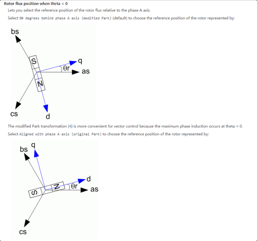
Park (Rev Park) transformation should be a difficult point for ST motor library to understand, because the operation result of the program is completely opposite to the common derivation result (the result of dq axis is exchanged). This is related to the coordinate definition of ST in the preface. For coordinate definitions, you can refer to Definition of coordinate system and electrical angle in FOC .
If defined according to this coordinate system, there will be a difficult problem to understand, because the common electrical angle is defined as the angle between d axis and alpha axis. Why can it be defined as the angle between q axis and alpha axis here? So the result won't go wrong?
In fact, to answer this question, we should answer it from the core idea of FOC. What is the purpose of FOC using Clarke transform and Park transform? It is to generate a 90 degree magnetic field of the leading rotor (d-axis, note that no matter how the electrical angle is defined, the definition of dq axis is always unchanged), or a 90 degree current of the leading rotor. So what's the use of the electric angle theta? In fact, it is only to indicate the direction of the current rotor, so as to generate a magnetic field 90 degrees ahead of the rotor, because the abc axis and alpha/beta axis are fixed, and the mutual conversion between the rotating coordinate axis and the fixed coordinate axis can be carried out only when the position of the magnetic field to be generated relative to these fixed coordinate axes is known. Therefore, the electrical angle can be defined arbitrarily. It can be the angle between q axis and alpha, the angle between d axis and alpha, or even the angle between d axis and the angle bisector (alpha axis and beta axis). Because the significance of the electrical angle is only to indicate the direction of the current rotor, and then generate a magnetic field 90 degrees ahead of the rotor, The magnetic field can be decomposed to a fixed coordinate axis, and then the generation of PWM can be controlled.
So why is the common definition the angle between d axis or q axis and alpha axis? In fact, it is very simple for the convenience of park and anti Park transformation, because at this time, it only needs to project each other between dq axis and alpha/beta axis, and when projecting × The coefficient of theta is the trigonometric value of theta. Therefore, it is also possible to define this included angle as the included angle between d-axis or q-axis and beta axis, which is also convenient for calculation. However, if it is defined as the included angle with other axes (such as alpha and beta angle bisectors), it is difficult to calculate the projection.
In short, remember: * * the final result of all transformations is to generate a magnetic field 90 degrees ahead of the rotor, and the electrical angle is only to provide the position of the rotor and facilitate the transformation of the magnetic field between various coordinate systems** This is also the core idea of FOC!
3.2. Why can an electrical angle pre calibration be performed when an electrical angle of - 90 degrees is given?
Why electrical angle calibration? It is also very simple, because the motor initially stops at any position, and the magnetic encoder has a reading (and the maximum probability is not 0). However, from the definition of the common coordinate system above, the zero degree of the electrical angle is defined as 0 degree when the q-axis or the d-axis is aligned with the alpha axis. At this time, the angle read by the encoder can be adjusted again × The number of poles is the offset electrical angle. When reading the electrical angle later, you only need to convert the mechanical angle actually read by the encoder into the electrical angle, and then subtract the pole logarithm, which is the real electrical angle. It can also be found here that the motor with P opposite poles can have p positions during initial alignment, which corresponds to p offset motor degrees. In fact, any offset angle can be used. (see another note for details)
Why can an electrical angle pre calibration be performed when an electrical angle of - 90 degrees is given? The answer is still related to the core idea of FOC, that is, FOC control should generate a magnetic field 90 degrees ahead of the rotor.
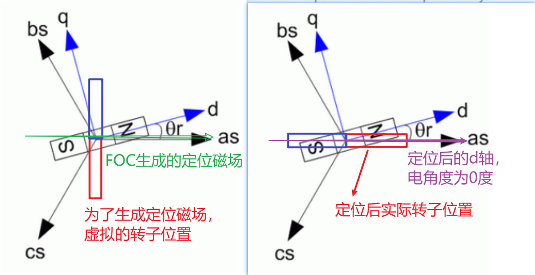
3.2.1. Electrical angle is defined as the included angle between d-axis and alpha axis
As shown in the figure below, the electrical angle is defined as the included angle between the d axis and the alpha axis. At this time, in order to calibrate the electrical angle, that is, to find the position where the electrical angle is 0 degrees, align the d axis and the alpha axis. At this time, the electrical angle is 0 degrees. In order to align the d axis with the alpha axis, a magnetic field in the alpha axis direction is generated. Since FOC control is used, its core is to control and generate a magnetic field 90 degrees ahead of the rotor. At this time, the virtual rotor should be 90 degrees behind the alpha axis, that is, when calibrating the electrical angle, the angle feedback is not from the encoder, but artificially given, because the purpose is to generate a desired magnetic field in a fixed direction, This attracts the rotor in this direction to align the electrical angle 0 degrees. Therefore, at this time, the virtual rotor is in the position shown in the figure, and the d-axis is also in this position. Then the electrical angle is the included angle between the d-axis and the alpha axis, which can be seen from the figure as - 90 degrees.
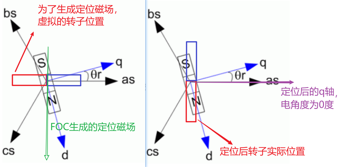
3.2.2. Electrical angle is defined as the angle between q axis and alpha axis
As shown in the figure below, the electrical angle is defined as the included angle between the q axis and the alpha axis. At this time, in order to calibrate the electrical angle, that is, to find the position where the electrical angle is 0 degrees, align the q axis and the alpha axis. At this time, the electrical angle is 0 degrees. In order to align the q axis with the alpha axis, a magnetic field in the beta axis direction is generated. Since FOC control is used, its core is to control and generate a magnetic field 90 degrees ahead of the rotor. At this time, the virtual rotor should lag 90 degrees behind the beta axis, that is, when calibrating the electrical angle, the angle feedback is not from the encoder, but artificially given, because the purpose is to generate a desired magnetic field in a fixed direction, This attracts the rotor in this direction to align the electrical angle 0 degrees. Therefore, at this time, the virtual rotor is in the position shown in the figure, and the d-axis is also in this position. At this time, the q-axis is in the direction of the generated FOC magnetic field, so the electrical angle is the included angle between the q-axis and the alpha axis. It can be seen from the figure that the electrical angle is - 90 degrees.
// Park has a big change problem, but it hasn't been understood yet
// solve! Finally understand why the Park transformation here is wrong!
// Definition of coordinate system: https://www.cnblogs.com/neriq/p/14800876.html
qd_t mc_park(alphabeta_t input, int16_t theta)
{
	qd_t output;
	int32_t d_tmp_1, d_tmp_2, q_tmp_1, q_tmp_2;
	trig_components local_vector_components;
	int32_t wqd_tmp;
	int16_t hqd_tmp;

	// Calculate the sin and cos values of the input angle
	local_vector_components = mc_trig_functions(theta);

	/*No overflow guaranteed  No overflow guarantee*/
	q_tmp_1 = input.alpha * ( int32_t )local_vector_components.h_cos;

	/*No overflow guaranteed  No overflow guarantee*/
	q_tmp_2 = input.beta * ( int32_t )local_vector_components.h_sin;

	/*Iq component in Q1.15 Format */
	wqd_tmp = ( q_tmp_1 - q_tmp_2 ) >> 15;  // Here is iq
	// Note that > > 15 here is still because the previous result is the operation of two Q15 formats, and the result is Q30 format, which needs to be converted to Q15 format again

	/* Check saturation of Iq */
	if ( wqd_tmp > INT16_MAX )
	{
		hqd_tmp = INT16_MAX;
	}
	else if ( wqd_tmp < ( -32768 ) )
	{
		hqd_tmp = ( -32768 );
	}
	else
	{
		hqd_tmp = ( int16_t )( wqd_tmp );
	}

	output.q = hqd_tmp;

	if ( output.q == ( int16_t )( -32768 ) )
	{
		output.q = -32767;
	}

	/*No overflow guaranteed*/
	d_tmp_1 = input.alpha * ( int32_t )local_vector_components.h_sin;

	/*No overflow guaranteed*/
	d_tmp_2 = input.beta * ( int32_t )local_vector_components.h_cos;

	wqd_tmp = ( d_tmp_1 + d_tmp_2 ) >> 15;

	/* Check saturation of Id */
	if ( wqd_tmp > INT16_MAX )
	{
		hqd_tmp = INT16_MAX;
	}
	else if ( wqd_tmp < ( -32768 ) )
	{
		hqd_tmp = ( -32768 );
	}
	else
	{
		hqd_tmp = ( int16_t )( wqd_tmp );
	}

	output.d = hqd_tmp;

	if ( output.d == ( int16_t )( -32768 ) )
	{
		output.d = -32767;
	}

	return (output);
}

/**
  * @brief Inverse park transform: Transform vqd in synchronous rotating coordinate system into V in stationary coordinate system_ alpha,v_ beta
  * @param volt_input: vqd
  * @param theta: Electrical angle value
  */
alphabeta_t mc_rev_park(qd_t volt_input, int16_t theta)
{
	int32_t q_v_alpha_tmp1, q_v_alpha_tmp2, q_v_beta_tmp1, q_v_beta_tmp2;
	trig_components local_vector_components;
	alphabeta_t volt_output;

	local_vector_components = mc_trig_functions(theta);

	q_v_alpha_tmp1 = volt_input.q * ( int32_t )local_vector_components.h_cos;
	q_v_alpha_tmp2 = volt_input.d * ( int32_t )local_vector_components.h_sin;

	volt_output.alpha = ( int16_t )( ( ( q_v_alpha_tmp1 ) + ( q_v_alpha_tmp2 ) ) >> 15 );


	q_v_beta_tmp1 = volt_input.q * ( int32_t )local_vector_components.h_sin;
	q_v_beta_tmp2 = volt_input.d * ( int32_t )local_vector_components.h_cos;

	volt_output.beta = ( int16_t )( ( q_v_beta_tmp2 - q_v_beta_tmp1 ) >> 15 );

	return (volt_output);
}